ASSEMBLY INSTRUCTIONS OPERATOR’S MANUAL PARTS LIST Classic Series Walk-Behind Leaf Blower Series 1 Models covered: Actual product may differ slightly from product pictured above Manual No. 7078079 (I.R.
1 preliminaries Congratulations! You have just purchased one of the finest pieces of outdoor power equipment on the market today. If properly cared for, your new blower will provide years of dependable service. Please read and follow this instruction manual carefully in order to get the most out of your new equipment.
2 safety rules regarding outdoor power equipment IMPORTANT! READ CAREFULLY THE FOLLOWING SAFETY RULES BEFORE ASSEMBLING OR OPERATING UNIT. TRAINING • Read, understand, and follow all instructions in the manual and on the unit before starting. If the operator(s) or mechanic(s) can not read English it is the owner’s responsibility to explain this material to them. • Become familiar with the safe operation of the equipment, operator controls, and safety signs. • All operators and mechanics should be trained.
2 safety rules regarding outdoor power equipment (cont.) • Watch for holes, ruts, or bumps. Uneven terrain could overturn the unit. Tall grass can hide obstacles. • Keep all movement on the slopes slow and gradual. Do not make sudden changes in speed or direction. Do Not • Do not start or stop on a slope. If tires lose traction, proceed slowly straight down the slope. • Do not turn on slopes unless necessary, and then, turn slowly and gradually downhill, if possible.
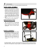
3 unit assembly Note: Please refer to Parts List for correct part identification and placement. FRONT WHEEL ASSEMBLY • • Attach left and right caster brackets to caster wheel using 3/8-18 x 2-1/4 bolt and lock nut. Insert bolt through hole in bracket. Place caster wheel onto bolt. Place other caster bracket onto bolt. Secure with lock nut. Do not over tighten. Wheel must rotate freely. Place caster brackets onto the threaded studs located near the discharge on the front of the machine.
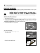
4 unit operation STARTING THE ENGINE IMPORTANT NOTE: The procedures outlined within this section are general guidelines, and are in no way meant to replace or supercede engine manufacturer’s operating instructions. In order to obtain optimum performance from your engine, refer to your engine manual. WARNING! IMPELLER IS MOUNTED DIRECTLY TO ENGINE SHAFT – STARTING ENGINE WILL RESULT IN IMMEDIATE HIGH-VELOCITY DISCHARGE.
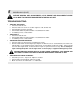
4 unit operation (cont.) STARTING THE ENGINE (cont.) • • Bracing unit with one hand on the upper handle and a foot on the right rear tire, firmly grasp recoil handle and pull briskly. You may have to pull several times before engine starts. (If engine fails to start within a reasonable amount of time, discontinue and check engine manual for further instructions.) Note: Do not allow recoil rope to snap back into recoil; damage to the rope or recoil could result.
4 unit operation (cont.) GENERAL RULES TO OBSERVE BEFORE AND DURING OPERATION: • • • • • • • Inspect your unit before each and every use. Check for worn, bent or broken components, loose fasteners, low or flat tires, etc., and repair or replace prior to operation. DO NOT OPERATE A MACHINE THAT IS WORN OR DAMAGED – SERIOUS INJURY OR DEATH CAN RESULT. Clear the entire work area of all debris that could cause damage to or become entangled in the unit.
5 maintenance BEFORE MAKING ANY ADJUSTMENTS, STOP ENGINE AND DISCONNECT SPARK PLUG WIRE TO PREVENT INADVERTENT STARTING OF UNIT. GENERAL: • • • • • • • • Follow implicitly the engine manufacturer’s recommendations for maintenance. Always keep your machine clean – especially the engine. Check all adjustments periodically. Also, periodically check that all fasteners are secure. Never make any adjustments to the unit until the engine is off and the spark plug wire is disconnected.
5 maintenance (cont.) BEFORE MAKING ANY ADJUSTMENTS, STOP ENGINE AND DISCONNECT SPARK PLUG WIRE TO PREVENT INADVERTENT STARTING OF UNIT. TROUBLESHOOTING: • • • UNIT WILL NOT START: • Check fuel and oil levels. • Check to make sure choke is set when engine is cold, off when hot. • Check throttle for proper operation. • Check intake baffle for jammed debris or accumulation of debris. • If condition persists, contact dealer. UNIT STALLS: • Check fuel and oil levels.
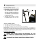
6 decal identification 75893 – EAR/NOSE/BREATHING PROTECTION REQUIRED – LOCATED ON SIDE OF BLOWER HOUSING 13010 – DANGER – KEEP HANDS AND FEET AWAY – LOCATED ABOVE BLOWER DISCHARGE 75760 – SNAPPER LOGO – LOCATED ON INTAKE BAFFLE (ON APPLICABLE MODELS) 33874 – DANGER – FLYING MATERIAL – LOCATED ON SIDE OF BLOWER HOUSING 1722551 – SIMPLICITY LOGO – LOCATED ON INTAKE BAFFLE (ON APPLICABLE MODELS) 6.
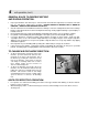
7 illustrated parts list 33 LBC6151BV
7 illustrated parts list (cont’d) Item 1 2 3 4 5 6 7 8 9 10 11 12 13 14 15 16 -17 18 19 20 21 22 23 -24 25 26 27 28 29 30 31 32 33 34 35 36 37 38 39 40 41 Part No.
7 illustrated parts list (cont’d) Item 42 43 44 45 46 47 48 49 Part No.
NOTES __________________________________________________________________________ __________________________________________________________________________ __________________________________________________________________________ __________________________________________________________________________ __________________________________________________________________________ __________________________________________________________________________ ________________________________________________________
Classic Series Walk-Behind Leaf Blower Series 1 Manual No. 7078079 (I.R.