
Installation manual


Simplicity 64 & Simplicity 126 INSTALLATION MANUAL.
Approved Document No: GLT.MAN-107
Issue : 1.04 Authorised: GH Date: 05/10/2004
PAGE 7
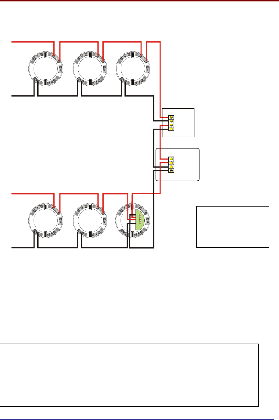
4.3 ADDRESSABLE LOOP WIRING DIAGRAM
The SIMPLICITY comes with one addressable loop. Addressable detectors, addressable call points,
addressable loop powered sounders and several other interface units can be connected to this loop.
A maximum of 126 devices can be connected to each loop. (64 for Simplicity 64)
L
1
I
N
L
1
O
U
T
E
A
R
T
H
L
2
-
R
---
++
IN OUT
L
1
I
N
L
1
O
U
T
E
A
R
T
H
L
2
-
R
L
1
I
N
L
1
O
U
T
E
A
R
T
H
L
2
-
R
L
1
I
N
L
1
O
U
T
E
A
R
T
H
L
2
-
R
Side A +ve
+
+
--
+
+
--
Side A -ve
L
1
I
N
L
1
O
U
T
E
A
R
T
H
L
2
-
R
L
1
I
N
L
1
O
U
T
E
A
R
T
H
L
2
-
R
Side B +ve
Side B -ve
FYREYE ADDRESSABLE
DETECTORS
FYREYE ADDRESSABLE
DETECTORS
ADDRESSABLE
CALL POINT
ADDRESSABLE
LOOP POWERED
SOUNDER
FYREYE
ISOLATING
BASE
A maximum of 32 loop-powered addressable sounders are permitted on the loop. There is no limit
(loop load permitting) to the number of sounder bases that can be connected to a loop. On the
Simplicity Panels, all Sounders are always configured as common sounders.
Short circuit isolators should be used to prevent loosing the whole loop in the event of a single short
circuit fault. They should be fitted to each zone boundary, such that any short circuit will only affect
the devices in 1 zone.
The termination of each detection circuit must be as indicated on the main PCB (See page 15). The
Earthing of the cable screens should be as shown on page 9.
Pre-Commissioning Cable Checks
1. +ve in to +ve out less than 24 ohms
2. -ve in to -ve out less than 24 ohms (may need to temporarily disable isolators to measure)
3. +ve to –ve greater than 500k ohm
4. +ve to Earth greater than 1M ohm.
5. -ve to Earth greater than 1M ohm.
6. +ve to –ve less than 50 mV pickup (on AC & DC scales)
Note that some Devices
(for example, a sounder
controller circuit) may
require a separate 24
volt supply to operate.