
Installation manual


Simplicity 64 & Simplicity 126 INSTALLATION MANUAL.
Approved Document No: GLT.MAN-107
Issue : 1.04 Authorised: GH Date: 05/10/2004
PAGE 3
1.SIMPLICITY OVERVIEW
The Simplicity is a 1-loop analogue addressable fire alarm control panel designed to EN54 part 2 & 4.
It is available in two versions. Simplicity 64 allows 64 devices to be connected, and divided into 4
zones. Simplicity 126 allows 126 devices to be connected, and divided into 8 zones.
They have been designed to give the advantages of an addressable system, with the “simplicity” of a
conventional system. To help achieve this, the Simplicity uses its LEDs as the Primary source of
information, so in most cases, there is no reason to look at the screen, or access any menus. The
screen is simply there to identify loop device fault locations, and to help in setting up the panel.
The Simplicity has been designed to only use addressable sounders (so that all devices sit on the
same wiring loop). All sounders on a Simplicity panel will activate on any alarm.
There are 2 types of sounder that the Simplicity panels can use; addressable or associated (sounder
base). Addressable are generally more expensive, but can be started and stopped quickly by the
panel. They have a maximum quantity of 32 per panel. Sounder Bases are generally less expensive,
but have a start /stop time of up to 8 seconds. They have no maximum quantity, and are only limited
by loop loading.
1.1 SETTING THE DEVICE ADDRESS (DETECTORS, CALL POINTS &
SOUNDERS)
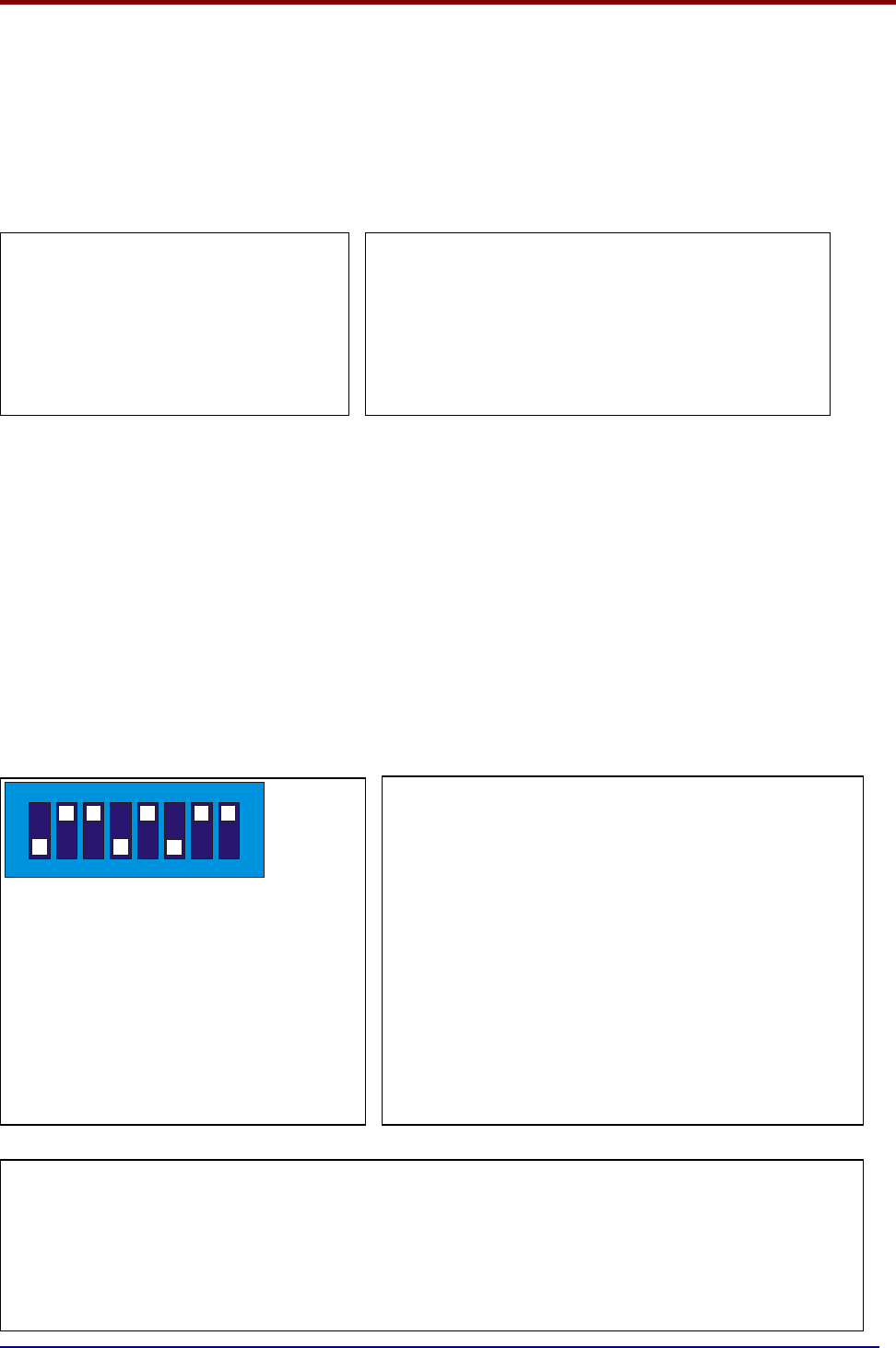
The device address is set with a dip switch on the rear of the device.
If you are not familiar with binary, check the
table on page 17, or use the following rule:
Switch 7 off = add 64,
Switch 6 off = add 32,
Switch 5 off = add 16,
Switch 4 off = add 8,
Switch 3 off = add 4,
Switch 2 off = add 2,
Switch 1 off = add 1.
The example shown would be:
switches 6, 4 & 1
=32 + 8 + 1 = Address 41
LIMITATIONS OF PRESET ZONE ALLOCATION
The main disadvantage of this method of zone allocation is the maximum zone capacity of 16 devices.
If a zone has more than 16 devices it will need to be split into smaller zones.
Similarly, a zone with only one device would leave 15 empty addresses on that zone.
This will not cause a problem if it is considered at the system design stage.
17
65
43
2
8
ON
The address setting is binary, with
the ON position being binary 0 , and
the OFF position being binary 1.
Switch 8 is not used for setting the
address, but sometimes has a
device specific function. (check
instructions that came with the
device)
Address 1-16 Zone 1 (Simplicity 64 & 126)
Address 17-32 Zone 2 (Simplicity 64 & 126)
Address 33-48 Zone 3 (Simplicity 64 & 126)
Address 49-64 Zone 4 (Simplicity 64 & 126)
Address 65-80 Zone 5 (Simplicity 126 only)
Address 81-96 Zone 6 (Simplicity 126 only)
Address 97-112 Zone 7 (Simplicity 126 only)
A
ddress 113-126 Zone 8
(
Sim
p
licit
y
126 onl
y)
To simplify commissioning further,
there is no zone allocation
programming. Instead the loop is split
into 8 zones (4 ON Simplicity 64), and
each device is assigned to a zone by
the address set with its 8 way dip
switch.