
Installation manual


Simplicity 64 & Simplicity 126 INSTALLATION MANUAL.
Approved Document No: GLT.MAN-107
Issue : 1.04 Authorised: GH Date: 05/10/2004
PAGE 26
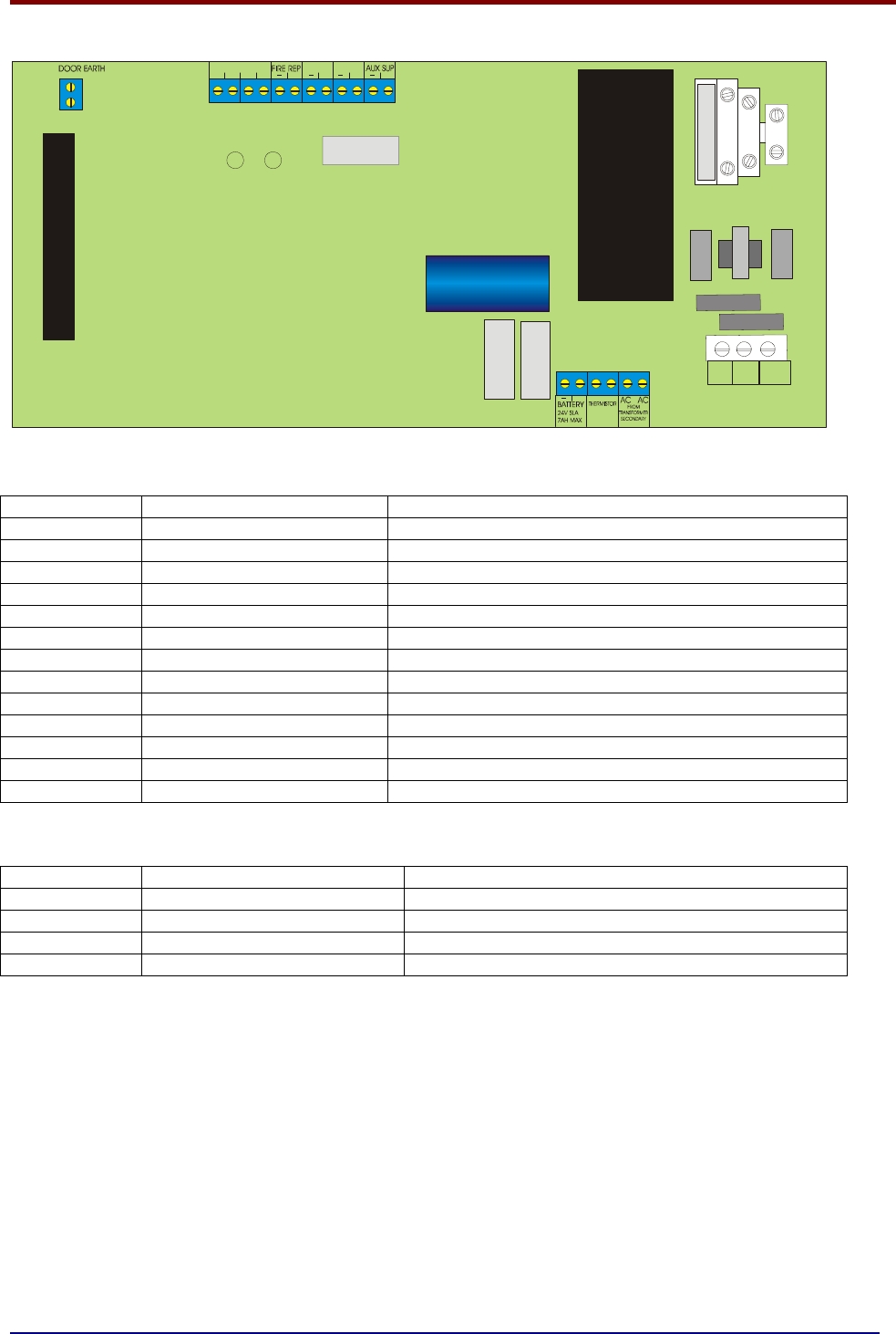
14. PCB TERMINATION CONNECTIONS.
LIVE NEUT- EARTH
RAL
MAINS FUSE
3A HBC CERAMIC
CONN29
FS1
FS2
FS3
1
2
3
4
5
6
7
8
9
10
LOOP WIRING FLT REP
CLASS
CHANGE
A- A+ B- B+
+ + + +
+
11
12
13
14.1 CONNECTIONS
Connection No Description Use
1 LOOP 1A +&- Connect to loop 1 side A
2 LOOP 1B +&- Connect to loop 1 side B
3 FIRE REPEAT OUTPUT 24V on fire (including test mode). Use to drive relay.
4 FAULT REPEAT OUTPUT Normally powered. 0V on fault. Use to drive FLT relay.
5 CLASS CHANGE Join terminals to activate sounders
6 AUX SUP +&- 24 volt supply. 100mA Max
7 BATTERY + & - Connect 2 x 12V SLA batteries in SERIES (ie 24V)
8 THERMISTOR Thermistor to prevent thermal overcharge
9 AC AC Connected to transformer secondary (30VAC)
10 CONN 27 EARTH connection to display PCB & SCREEN TAG
11 CONN 3 50 way ribbon cable to display PCB
12 CONN 29 Filtered mains to transformer
13 CONN 6 MAINS TERMINAL BLOCK
14.2 FUSES
FUSE NO DESCRIPTION RATING
FS1 Charger Fuse 1.6A time delay 5 x 20mm glass
FS2 Battery Fuse 1.6A time delay 5 x 20mm glass
FS3 Aux Supply 100mA time delay 5 x 20mm glass
INLET FUSE Mains Protection Fuse 2.0A Quick Blow HBC 5 x 20mm ceramic