
Installation manual


Simplicity 64 & Simplicity 126 INSTALLATION MANUAL.
Approved Document No: GLT.MAN-107
Issue : 1.04 Authorised: GH Date: 05/10/2004
PAGE 10
4.5 AUXILIARY INPUT WIRING EXAMPLES
There is one non-latching auxiliary input connection on the Fire Alarm Panel.
Class Change Input (CC): This will energise all alarm outputs continuously when the CC terminals
are shorted together. (This includes the addressable sounders, sounder bases. The auxiliary fire
relay driver is NOT activated by the Class Change input.)
Typical auxiliary input wiring options
CLASS
CHANGE
2nd Fire Alarm
AUX FIRE RELAY
CM
NO
CLASS
CHANGE
The termination for the above inputs must be as indicated on the main PCB (See page 15). The
Earthing of the cable screens should be as shown on page 9.
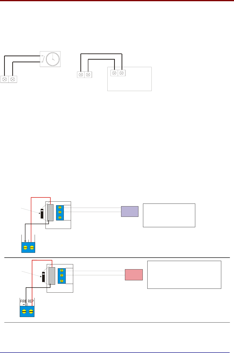
4.6 AUXILIARY OUTPUT WIRING (24V Relay Drive Outputs)
Auxiliary Fire Output (AUX): Supplies 24V in any fire condition. This is used to drive a 24 volt relay
(coil voltage), which can be connected to emergency lights, local fire fighting equipment such as
sprinkler systems, magnetic door holders, air conditioning shut off, etc. More than one relay can be
connected to this output if required.
Fault Output (FAULT): Gives 24V in the quiescent condition, and 0V in a fault condition. This
ensures failsafe operation even in the event of total power loss. More than one relay can be
connected to this output if required.
Typical auxiliary output wiring
Trigger I/P
FLT REP
+
RELAY OUTPUT
NO CM NC
RELAY
FAULT
INDICATION
DEVICE
FIT BACK-EMF
DIODE ACROSS
RELAY COIL
+
Trigger I/P
RELAY OUTPUT
NO CM NC
RELAY
A
UTODIALLER
FIT BACK-EMF
DIODE ACROSS
RELAY COIL
The termination for the above inputs must be as indicated on the main PCB (See page 15). The
Earthing of the cable screens should be as shown on page 9.
The fault relay is used to
connect to a remote
indication device
The fire relay can be used to connect
to various devices which are activated
on a fire alarm. Eg. Auto dialer ,
magnetic door release (24V), sprinkler
system etc.