
Product Manual
15
Operating the Tractor
Mower Deck Removal & Installation
Removing the Mower Deck
1. Park tractor on a hard, level surface such as a
concrete floor. Turn off PTO switch and engine,
remove the key and apply parking brake.
2. Place mower in the lowest cutting position using the
mower height adjuster (B, Figure .
3. Place the attachment lift in the lowest position (A,
Figure 7 or 8).
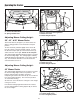
4. Move idler arm (A, Figure 5) to relieve belt tension.
Remove belt from PTO pulley (B).
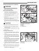
5. Remove hair pin (B, Figure 4) and washer (C).
Disconnect the lift cable & pin (D) from the lift hole(s)
(A). Re-install washer (C) and hair pin (B) to prevent
loss.
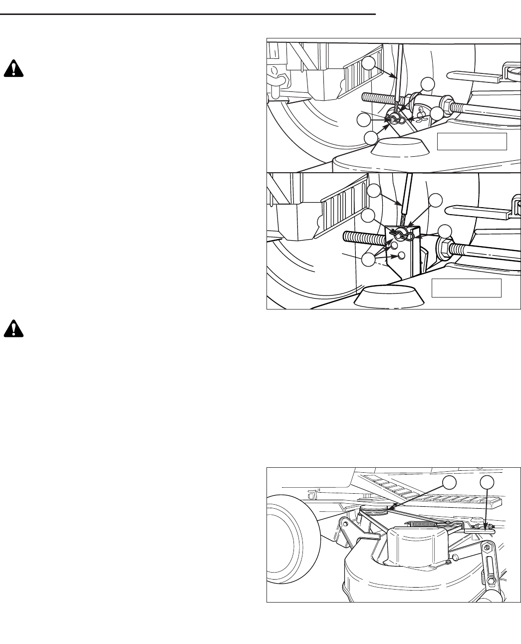
6. Turn wheels straight ahead. Pull back on spring-
loaded lever (B, Figure 6) and lift mower hitch off of
the tractor brackets.
7. Turn wheels fully left, and slide mower deck out right
side of tractor.
Installing the Mower Deck
1. Park tractor, shut off PTO and engine, remove the
key and apply parking brake. Turn the wheels fully to
the left.
2. Place mower height adjuster (B, Figures 7) in the
lowest cutting position. Place the mower lift lever (A)
in the lowest position. Slide mower deck under right
side of tractor so that mower hitch is aligned with the
front tractor hitch.
3. Turn wheels straight. Pull back on the spring-loaded
lever (B, Figure 6) while lifting up on the mower hitch.
Install mower hitch onto tractor hitch brackets (A).
When properly installed, the spring-loaded lever
should seat fully underneath the brackets.
4. Connect the lift cable & pin (D, Figure 4) to the tractor
lift hole(s) (A) using the flat washer (C) and hair pin
(B).
Note: On models with multiple holes use the same hole
(upper, center or lower) on each side to keep deck level.
5. Move idler arm (A, Figure 5) to relieve belt tension.
Install belt onto the PTO pulley (B).
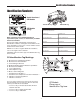
WARNING
Engage parking brake, disengage PTO, stop
engine and remove key before attempting to
install or remove the mower.
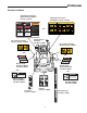
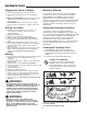
Figure 5. Removing & Installing Belt
A. Idler Arm
B. PTO Pulley
B
A
CAUTION
The muffler and surrounding areas may be hot.
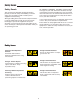
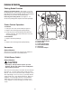
Figure 4. Lift Cable
(Viewed from underneath right side of tractor)
A. Lift Hole(s), 11/32” (8.7mm)
B. Hair Pin
C. Washer
D. Lift Cable & Pin
B
C
D
D
B
C
D
D
A
A
Early Models
Later Models