
Instructions / Assembly

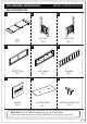
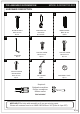
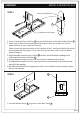
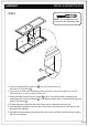
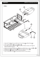
Table Of Contents

8/14
ASSEMBLY
STEP 1
1. Screw 2 threaded Cam Lock Pins 2 into pre-drilled holes on the back of Back Panel D .
2. Screw only to where the threading ends and ensure they are straight. Do not use
excessive force to over-screw cam lock pin.
Note: please pay close attention to the location of the 2 small pre-drilled holes which (
accommodate the lid support. They need to be on the same side as the Pre-drilled
holed of . )hinges
3. Align threaded cam lock pins in Panel D to the 2 pre-drilled holes leading to the
round cam lock inserts in Divider F .
4. Ensure alignment mark on cam lock insert point to exposed cam lock pin.
5. Use flathead screwdriver to turn cam lock inserts to ensure top of cam lock pin and
panels fit flat together.
6. Use flathead screwdriver to tighten cam lock ½ turn and feet it lock securely in place.
Do not over-tighten.
MODEL # AXCRART13-RUS
Small pre-drilled holes
Pre-drilled holed of Hinges
2
F
D
STEP 2
G
D
G
D
F
F
1. Inserted Bottom Panel G to groove of the Back Panel D .
Up
S
ide
/
V
er
t
i
cal
Up
S
i
d
e /
V
ertica
l
Up
S
ide / V
er
t
i
ca
l