TM TM
TM TM
PART DESCRIPTION LEFT SIDE QTY 1 RIGHT SIDE QTY 1 BACK PANEL QTY 1 F G H NEED HELP? For help with assembly or if you are missing a part, Please call customer service at 1-866-518-0120 ext.
PART DESCRIPTION IL IL J K NEED HELP? For help with assembly or if you are missing a part, Please call customer service at 1-866-518-0120 ext.
HARDWARE DESCRIPTION 2 ALLEN KEY QTY 1 4 PLASTIC CAP QTY 6 Required Flathead screwdriver Phillips screwdriver Not Included 7/18
MODEL # 3AXCHRP-08 COMPONENTS-KEY DIAGRAM B E F R D L F D G C G J R K L H
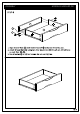
MODEL # 3AXCHRP-08 ASSEMBLY R H L 5 1. Attach four Cam Lock Pins 5 to back of Drawer Front H . 2. Align Cam Lock Pins with pre-drilled holes and attach Drawer Sides IL , IR . 3. Insert two Cam Locks 5 into pre-drilled holes on each Drawer Side IL , IR . 4. Use flathead screwdriver to secure Cam Locks.
MODEL # 3AXCHRP-08 ASSEMBLY J R 1 K 3 L
MODEL # 3AXCHRP-08 ASSEMBLY 5 L D R D L 1 R 3 C 1. Attach Bottom C to Sides AL , AR using six Allen Key Screws 1 (three Screws on each Side). 2. Use Allen Key 3 to tighten Screws. Do not over-tighten.
MODEL # 3AXCHRP-08 ASSEMBLY 1 3 G C G 3 2
MODEL # 3AXCHRP-08 ASSEMBLY 5 B L R
MODEL # 3AXCHRP-08 ASSEMBLY 4 B E
7 L F R F 6 6 6 F
8 8
TM TM WARRANTY