
Installation guide


8
Overview
Configuring the DACT consists of:
•
Setting the correct communication mode
•
Specifying whether the DACT is in Test mode
•
Specifying whether the DACT should be ready to download new programming data
•
Setting the device address
This section covers all of these settings.
Setting the COMM
switch
Make sure switch SW1 is in the DOWN position. This specifies the 4100 communications mode.
Setting the Test
Switch
Make sure switch SW2 is in the DOWN (off) position. This should be used for testing the DACT,
and then returned to the DOWN position. See “Testing.”
Setting the
Programmer
Switch
To download data, switch SW3 must be in the UP position. During normal DACT operation,
SW3 must be in the DOWN position. See the section on Testing and Compatibility.
Setting the
Address
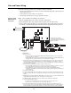
The device address is set via DIP switch SW4, which is a bank of eight switches. From left to
right (see Figure 4) these switches are designated as SW4-1 through SW4-8. The function of
these switches is as follows:
•
SW4-1. This switch sets the baud rate for the internal 4100 communications line
running between the card and the 4100 CPU. Set this switch to ON.
•
SW4-2 through SW4-8. These switches set the card’s address within the 4100 FACP.
Refer to Table 3 for a complete list of the switch settings for all of the possible card.
addresses.
Note: You must set these switches to the value assigned to the card by the Programmer.
Figure 4. DIP switch SW4
2))
21
&200%$8'5$7(
6:,7&+6:
0867%(6(77221
)25',36:,7&+(66:
7+528*+6:6(77+(
&$5'$''5(66),*85(
6+2:6$1$''5(662)
Configuring the DACT
Continued on next page