
Installation guide


4
C900V2 Ethernet
Transmission (UL
only)
The DACT receives system status messages from the 4100U/4100ES using the codes listed on
page 17. It then communicates the information over an Ethernet connection to a DACR at the
central station. The telephone connections on the DACT are connected together; R1 (TB1-2) to
R2 (TB2-2) and T1 (TB1-3) to T2 (TB2-3). Then a single pair is connected to the C900V2.
Note: Since an actual telephone line is not used, TB1-1/TB1-4 and TB2-1/TB2-4 are not used.
The correct IP address and other modes are programmed into the C900V2, refer to the Installation
and Programming manual supplied with the C900V2.
When the DACT goes off-hook, the C900V2 sends a dial tone to the DACT. The panel dials the
number of the central station and the C900V2 sends all the correct tones so that the DACT
believes it is connected to the central station through the telephone line. Upon receipt of the infor-
mation, the C900V2 sends the information to the central station through the Ethernet connection.
The C900V2 must be mounted within 20 feet of the FACP and in the same room as it. It must also
be enclosed in a conduit or be equivalently protected against mechanical changes.
_________________________________________________________________________________
Illustration
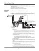
Figure 1 is an illustration of Serial DACT card 566-787. The circuit boards for all DACTs
described in this publication are identical.
Figure 1. Serial DACT card 566-787
6&5(:
7(50,1$/6
3+21(/,1(
&211(&7,216
'(9,&($''5(66
6:,7&+6:
&2007528%/(
/('/('
3$11(/7528%/(
/('/('
32:(5&200
7528%/(/('
/('
352*5$00(5
6:,&+6:
352*5$00(5
&211(&7,21
723&3
86&$102'(
-803(5
228&200
&211(&7253
58,&211(&725
3
58,&211(&725
3
58,&200
6:,7&+6:
6(/)7(67
6:,7&+6:
Introduction (continued)
Continued on next page