
Installation guide


3
Overview
Digital Alarm Communications Transmitter’s (DACT) are option cards that mount within 4100
Fire Alarm Control Panels (FACP).
The 4100/4120-0155 Serial DACT, available for the 4100 (non-4100U/4100ES) only, can be
programmed to notify the central station when specified events occur, or to report changes to a
specific point’s status.
The 4100-6052 DACT, available for the 4100U and 4100ES, has four main functions:
•
Notifying the central station when specified events occur
•
Reporting changes to a specific point’s status to the central station
•
Connecting to a DSC TL300 transmitter for connection to a central station via Ethernet line
(UL and ULC)
•
Connecting to a Bosch C900V2 transmitter for connection to a Central Station through the
Ethernet line (UL only)
Phone Line
Transmission
The DACT receive system status messages from the host FACP, and communicate the informa-
tion over the public telephone network to a Digital Alarm Communications Receiver (DACR) at
the central station.
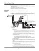
The DACT is connected to two telephone lines, which are not required to be "dedicated" to the
fire alarm. They may be connected to other telecom equipment, but the DACT must be wired
electrically "first" in the chain as shown in Figure 5. The telephone lines must be wired to DACT
terminals TB1-2/TB1-3 and TB2-2/TB3-3 to ensure that the DACT can disconnect other telecom
equipment in case the phone line is in use during an emergency. The other telecom equipment is
wired to TB1-1/TB1-4 and TB2-1/TB2-4.
The DACT is programmable for pulse or tone dialing , see the ES PanelProgrammer’s Manual
(574-849) for the programming instructions.
The DACT detects whether or not a telephone line is connected to both inputs. A 4100 system
trouble is signaled, both audibly and visibly, if either line is disconnected.
TL300 Ethernet
Transmission (UL
and ULC)
The DACT receives system status messages from the FACP using CID codes only. Then, it
communicates the information over an Ethernet connection to a DACR at the central station. The
telephone connections on the DACT are connected together, (R1 (TB1-2) to R2 (TB2-2) and T1
(TB1-3) to T2 (TB2-3). Then, a single pair is connected to the TL300 (T1 (TB1-2 of DACT) to
T1 and R1 (TB2-3 of DACT) to R1). Since an actual telephone line is not used, TB1-1/TB1-4 and
TB2-1/TB2-4 are not used. The correct IP address and other modes are programmed into the
TL300, see programming section later in this manual.
When the DACT goes off-hook, the TL300 sends a dial tone to the DACT. The panel dials the
number of the central station and the TL300 send all the correct tones so that the DACT believes
it is connected to the central station via a telephone line. Upon receipt of the information the
TL300 sends the information to the central station via the Ethernet connection. The TL300 must
be mounted within 20 feet, in the same room, in conduit. Power for the TL300 comes from the
FACP. Refer to T-Link TL300 Installation Manual 29034531 for further details.
Introduction