
Installation guide


12
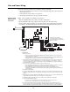
Wiring the DACT
to the C900V2
DACT (UL only)
Figure 7. Wiring the DACT to the C900V2 DACT (UL only)
(2/5
&9
%RVFK $( HQFORVXUH
DZJ
P$ PD[LPXP
6HH QRWH
(7+(51(7
3
3
3DQHO
7HOFR
6
6HH QRWH
5-
VHH QRWH
5HG
*UHHQ
29
29
287
287 287 287 ,1
,1 ,1 9
6HHQRWH
6HHQRWH
DZJ
86
&$1
6HULDO'$&7
7%
7%
3
3
3
36: 6: 6:
6:
6:
/('
/('
/('
3
Data and Power Wiring (Continued)
Figure 7 Notes:
1. A Bosch C900V2 in a
Bosch AE2 enclosure must
be mounted within 20 feet
of the FACP and be in the
same room as it. The wiring
to the FACP must be
enclosed in the conduit or be
equivalently protected
against mechanical damage.
The cabinet must be
grounded.
2. Wire the C900V2 to the
FACP’s IDC to monitor
LAN and board failure.
Make connections as shown.
3. Consult installation guide
F01U003472 for program-
ming and setup instruction
for the C900V2
4. T1AUX , R1AUX,
T2Aux and R2AUX are not
used. Auxiliary equipment
cannot be used either.
5. Wire the C900V2 to the
4100U/4100ES SPS Aux
Power terminal, TB3-1 0V,
TB3-2 +24. Maximum
current draw of C900V2 is
280ma.
6. Wire jumper TB1-2 to
TB2-2 and TB2-3 to TB3-3.