
Installation guide


11
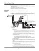
Wiring the DACT
to the TL300
Wire the DACT to the TL300 in accordance with Figure 6 and Figure 7.
Figure 6. Wiring the DACT to the TL300
#18-22 awg
150mA max
See note 4
#18 - #26 awg
#18 - #22 awg
See note 3
#18 - #26 awg
N
otes:
1. Panel containing the TL300 to be mounted within 20 feet of the FACP and
mounted in the same room. The wiring to the FACP to be in conduit.
2. Connect to the FACP, IDC to monitor Ethernet connection failure.
3. Connect to FACP, Relay N.O. contact. Relay programmed to energize when
there is a telephone Line 1 or 2 trouble in the Serial DACT.
4.
T-Link TL300
12V GRNTX
RX RED
BLK
YEL
PGM1
PGM2
IN1 IN2
IN3
IN4
T1
R1
Network
GND
GND GND
GND
Earth
DSC FC5003 Cabinet
#18 - #22 awg
See note 2
3
4
IAM
EOLR for IDC
To Auxiliary Power terminals 24V and 0V of the FACP SPS.
See note 4
US
CAN
Serial DACT
0566-787
TB2TB1
P1
P2
P3
P4SW1 SW2 SW3
SW5
SW4
LED3LED1 LED2
P6
11
Data and Power Wiring (Continued)