
Installation guide


10
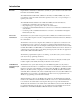
Wiring Guidelines
Review the following guidelines before wiring P1 and P4 of the DACT.
•
If U.T. motherboard 565-274 or 565-213 is wired to the DACT, jumper P4 on the motherboard
must be at position 13.
•
Unless otherwise noted, wiring is not supervised.
•
Cut and strip wire harnesses to the proper length, if required.
Wiring an Serial
DACT Card Into
the System
Note: Unless otherwise noted, wiring is not supervised.
1. Wire the Serial DACT into the system in accordance with Figure 5.
2. Route the TELCO cables using separate paths from panel exit to RJ-31X modules
3. Use the cable tie-wraps (supplied) to provide strain relief for these cables. Secure the cables to
any standoff or metal fixture along the cable run between the Serial DACT and the panel exit.
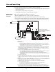
Figure 5. Serial DACT card 0566-787
Figure 5 Notes:
1. Factory connections:
•
4100: Connect to the nearest 4100/4120 Motherboard P2/P3 plugs: white wire socket to P3, blue wire
socket to P2. Observe orientations.
•
4100U/4100ES: Connect to the nearest 4100/4120 Motherboard P2/P3 plugs or /4100ES Motherboard P7/
P8 plugs: white wire socket to P7, blue wire socket to P8. Observe orientations.
2. Power-limited wiring. Route the TELCO cables from the terminal blocks to the left side of panel, and exit at the
top-left of enclosure. Using the 2080-9046 Harness (7 ft. cable), -9047 Harness (14 ft. cable), or equivalent,
connect to the TELCO jacks. Splice as required (using a minimum of 22 AWG wire) to complete the desired span.
The TELCO wiring is supervised.
3. Cable connection to Serial DACT Programmer (only present during set-up).
•
4100: Switch SW3 must be placed in the ON position for the download. When the download is completed,
place switch SW3 in the OFF position for normal operation. Cable is not supervised.
•
4100U/4100ES: Connection to the Programmer is not required for 4100U/4100ES installations.
Programmer switch SW3 must remain in the OFF position. SDACT program is updated automatically after
system download.
4. Card Address Switch (SW4).
5. Programmer Switch (SW3). Slide switch SW3 to the ON (up) position to program and download. Return to OFF
position for normal operation. Note: “Up” and “down” switch references become “in” and “out” after the board is
installed.
6. SDACT Manual Test Switch (SW2). Slide switch SW2 to the ON (up) position for a manual test that will dial and
attempt DACR communication. Return to the OFF position for normal operation.
7. COMM Switch (SW1). Switch SW1 must be in the down position for 4100/4120 communication.
8. U.S./Canada Operating Mode Jumper:
•
U.S. mode is selected when there is no jumper or jumpers are connected to pin 1 and 2.
•
Canada mode is selected when jumpers are connected to pin 2 and 3
9.
Bootloader Switch (SW5). The bootloader switch should be left in the off position for SDACT operation. If
necessary, It can be used to allow a field upgrade to the SDACT firmware. Instructions for using the bootloader
will be included with any required firmware upgrades. (See Technical Support web site for future availability.)
7['2XW
&RPPRQ
5[',Q
56
/LQH/LQH
86
&$1
6HULDO'$&7
7%
7%
3
3
3
36: 6: 6:
6:
6:
/('
/('
/('
3
Configuration not used when
connected to a TL300 or a C900V2.
See the following pages for TL300 and
C900V2 connections
Data and Power Wiring