4004 Fire Alarm Installation/Operation Instructions 574-074 Rev. C Technical Manuals Online! - http://www.tech-man.
Technical Manuals Online! - http://www.tech-man.
Copyright and Trademarks Copyright © Simplex Time Recorder Co., 1999. All rights reserved. Printed in the United States of America. Information in this document is subject to change without notice. No part of this document may be reproduced or transmitted in any form or by any means, electronic or mechanical, for any purpose, without the express written consent of Simplex Time Recorder Company. Simplex WALK TEST™ system test is protected under U.S. Patent # 4,725,818.
Technical Manuals Online! - http://www.tech-man.
Table of Contents Chapter 1 4004 System Overview Overview .........................................................................................1-1 Environmental .................................................................................1-2 Ground ............................................................................................1-2 Power Input .....................................................................................1-2 Battery Standby...........................................
Technical Manuals Online! - http://www.tech-man.
Chapter 1 4004 System Overview Overview The 4004 Fire Alarm Control Panel (FACP) is a general alarm, battery-backed, electrically supervised system capable of operating two Notification Appliance Circuits (NACs) and monitoring two Initiating Device Circuits (IDCs) with expansion capability of up to 8-IDCs. The 4004 FACP is capable of automatically controlling auxiliary equipment such as fire doors and fans during a fire condition.
Environmental The 4004 is designed to operate in the following conditions: • • 32 - 120° F /0 - 49° C UL - 85% relative humidity (non-condensing) ULC - 93% relative humidity (non-condensing) Ground The 4004 FACP must be grounded properly. Readings of less than 0.70 VAC must be measured between ground and neutral. A system ground needs to be provided for Earth Detection and transient protection devices.
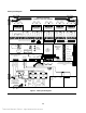
4004 System Diagram 2 3 1 (-) (+) 4 SIG 2 (-) 3 SIG 1 (+) 2 1 (-) (+) 4 SIG 2 (-) 3 SIG 1 (+) 2 1 (-) (+) 4 SIG 2 (-) 3 (-) 2 1 SIG 1 (+) 4 (+) (+) 3 SIG 2 (-) (-) 2 1 SIG 1 (+) SIG 2 (-) SIG 1 (+) CONDUIT ENTRY POWER LIMITED WIRING 4 CLASS A CLASS A CLASS A CLASS A CLASS A CARD 565-585/789 CARD 565-585/789 CARD 565-585/789 CARD 565-585/789 CARD 565-585/789 LP 0V (-)AUX (-)RET (-) ZN PWR (-)RET (-)AUX (-)AUX (-)RET (-) ZN PWR (-)RET (-)AUX (-
This page left intentionally blank Technical Manuals Online! - http://www.tech-man.
Chapter 2 Requirements and Accessories Regulatory Requirements NFPA Standards The 4004 Fire Alarm System is listed/approved for the following listing categories: Listed to UL Standard 864 for the following system types: • UL 864 Power-Limited Fire Alarm Control Unit. • Local (formerly NFPA 72A). Requires the sounding of an alarm via the listed notification appliance(s). • Auxiliary (formerly NFPA 72B). Requires the 4004-9809 City Circuit Module.
Installation Requirements Optional Accessories Most NFPA Codes and Standards referenced publications are listed below. You must be familiar with codes, as well as any applicable local codes and standards, when installing a fire alarm system.
Chapter 3 Installation IMPORTANT: Notify appropriate personnel (building occupants, fire department, or monitoring facility, etc.) of the installation. Before beginning installation, ensure that you are thoroughly familiar with these instructions and all applicable regulatory requirements. (Refer to Chapter 2 - Requirements and Accessories.
Back Box (Continued) Description Weight (See Note 5) Height Rough Opening (See Note 2) Width Size Box Door Box Door Box Door Height Width 4004 6.5 lb 3.5 lb 16-1/8 in. 17 in. 14-1/2 in. 16-1/8 in. 16-1/8 in. 14-1/2 in. CAUTION: Enclosure must be level and plumb when installing the back box. Notes: 1. The box can be mounted semi-flush with the surface of the wall (the cabinet protrudes approximately 3/8”). Dimensions shown are typical for all surface and semi-flush installations.
System Modules (Continued) The selectable IDC types are as follows: Fire Monitor - For this point type, an alarm is defined as a direct short or current-limited condition across the initiating device circuit. An open circuit is a trouble condition. Alarm Verification - This point type causes an immediate alarm with a direct short across the IDC. If current-limited circuit condition exists, the alarm verification sequence is started. An open circuit is a trouble condition.
System Modules (Continued) CONNECT TO P5 ON 565-573 565-585 OR 565-789 CLASS A BD 733-885 565-585 OR 565-789 CLASS A BD 2 POINT 733-875 2 POINT 2 OR 565-585 OR 565-789 CLASS A BD 2 J1 565-585 OR 565-789 CLASS A BD 2 POINT 2 POINT 2 J1 565-585 OR 565-789 CLASS A BD 2 POINT 2 2 J1 J1 J1 565-577 CITY BOARD 565-599 DACT BOARD DETAIL TELEPHONE CONNECTORS A TB1 MEMBRANE SWITCH 1 J1 P1 J2 J1 J1 J2 636-746 P1 J1 XFORMER ASSY 636-699 220/240V J2 P1 3 3 J3 565-589 OR 565-613 ID
System Modules (Continued) The two NACs available with the base 4004 panel are rated at 2-amperes at 24-volts for each circuit. Power-limiting is from the 4004 system power supply. Additional NACs are added using the 4009 NAC Power Extender. The 4004 is a general alarm system, meaning that both NACs are energized on any alarm. Selection of “On Until Silenced” or “On Until Reset” is possible using jumper switch settings (see the section in this chapter titled “Jumper Settings/Service Switches).
System Modules (Continued) 2-IDC Expander (Relay Base) [565-612] (high current) - This module is identical to the 2-IDC expander described above, except that it supports higher current initiating devices (3 mA) and it supports a single relay base. It also uses a 3.3 K Ohm EOL resistor that may be desired in retrofit applications. 4-IDC Expander Module [565-589] (low current) - The 4004 supports only one 4-IDC Expander module in a system.
System Modules (Continued) CCDACT Module [565-626] - The DACT Module uses the same CPU card connector as the City Connect Module, meaning a system may have either a DACT Module or a City Connect Module. A DACT trouble output will cause a 4004 system trouble, and is indicated on the seven segment display as a "City/DACT Trouble" ("C"). Mounting conforms to Power Limited requirements. The auxiliary Alarm output is on-until-reset. The trouble output is active until the trouble condition is cleared.
Jumper Settings/Service Switches (Continued) The 4004 has the following service switches for servicing and testing the system (see Figure 1): Zone Disconnect Switch - “ON” for normal operation and “OFF” to disconnect zone. To disconnect a 4004 zone from a normal state, slide the Zone Disconnect Switch for any zone in alarm to the “OFF” position. this transfers the zone(s) from a normal condition to a zone disconnect trouble condition. Press the “ACK” key to acknowledge the trouble condition(s).
Programming Instructions No special programming equipment is needed to configure the 4004 system. If no programming options are selected, the panel operates with the following default conditions: • System configured for 8-IDC, CITY/DACT, Annunciator Interface. • All IDCs are FIRE type, no Alarm Verification or Fire/Supervisory points. • NAC 1 is coded Temporal until Silence (no cut out or inhibit). • NAC 2 is on steady until Reset. • Abnormal condition reminder active.
Programming Instructions (continued) TROUBLE FIRE ALARM SUPERVISORY ZONE ALARM SILENCED ACK ALARM SILENCE SCROLL THRU OPTIONS SCROLL THRU SETUPS PROGRAM = NUMBER OF ZONES AC POWER SYSTEM RESET CURRENT SETUP SELECTION = DEFAULT Number of zones in the system. = ZONES = ZONE 1 = ZONE 2 = FIRE MONITOR = ZONE 3 = ALARM VERIFICATION = ZONE 4 = FIRE/SUPERVISORY = ZONE 5 = TROUBLE ONLY = ZONE 6 = STYLE C Defines the initiating Device point type.
Chapter 4 Operating Instructions Front Panel Operation The user interface consists of controls and indicators that provide support to 4004 fire alarm functions. The user interface indicates alarm, supervisory, trouble, power on, and alarm silenced conditions (shown in Figure 5). The purpose of the controls and indicators are in the Operator Key Definitions section of this chapter. TROUBLE FIRE ALARM SUPERVISORY ZONE ALARM SILENCED ALARM SILENCE ACK SYSTEM RESET AC POWER Figure 5.
Operator Key Definitions (Continued) 5. Trouble Display - The “TROUBLE” LED is a yellow, seven-segment that is used to indicate IDC, NAC, City Circuit, Power Supply, AUX output, and various system trouble conditions. The IDC troubles are displayed using numerals 1 through 8, other troubles are displayed alphabetically (See Table 2 for a list of troubles indicated on the yellow “TROUBLE” display). The scrolling operation is identical as described in the “FIRE ALARM ZONE” display.
Operator Key Definitions (Continued) The “ACK” key is also used to perform a lamp test on the system LEDs and displays. When the “ACK” key is pressed for five seconds, the red and yellow, seven-segment displays (all segments), System tone-alert and Power On, Alarm Silenced, and Supervisory LEDs turn ON and remain ON until the “ACK” key is released. 8. System Initialization (Power-Up) Alarm Silence Key - The “ALARM SILENCE” key de-energizes NACs configured as “On Until Silence.
Supervisory Conditions A Fire/Supervisory point distinguishes between Fire Alarm and Supervisory conditions on a single circuit. When water is flowing in a sprinkler system, an Alarm is indicated, but if a sprinkler or water pump valve has been closed, a “SUPERVISORY” service condition is indicated. This condition is distinctly different from a trouble or alarm condition. The yellow “SUPERVISORY” LED flashes and the tone-alert sounds until the condition is acknowledged via the “ACK” key.
System Testing (Fire Drills) (Continued) The optional city module has disconnect switch(s) SW1 (City Circuit 1) and SW2 (City Circuit 2) that disables the city circuit if desired. If the AHJ wanted to test the city box, the city circuit disconnect switch(s) would not be enabled. A system wired with the optional DACT module must have system testing coordinated with the Central Station operator and the AHJ. To initiate a test with the 4004, activate an initiating device (pull station, smoke detector etc.).
This page left intentionally blank Technical Manuals Online! - http://www.tech-man.
Chapter 5 Glossary of Terms Glossary of Terms Alarm - A warning of fire danger. Alarm Signal - A signal indicating an emergency requiring immediate action, such as a signal indicative of fire. Alarm Verification - A feature to reduce unwanted alarms wherein smoke detectors must report alarm conditions for a minimum period of time. Alarm Verification also confirms alarm conditions within a given time period, after being reset to be accepted as a valid alarm initiation signal.
Glossary of Terms (Continued) Initiating Device - A system component that originates transmission of a change of state condition, such as a smoke detector, manual fire alarm box, supervisory switch, etc. Initiating Device Circuit (IDC) - A circuit to which automatic or manual initiating devices are connected where the signal received does not identify the individual device operated.
Glossary of Terms (Continued) States - The state of an IDC is determined by the physical condition of the wiring and devices connected to the terminal block. There are four states associated with an IDC: • Short (0-200 ohms). • Current-limited state (400-820 ohms), across the initiating device circuit. • Normal state (defined as the end-of-line resistor in place with the full range of line resistance and detector load).
This page left intentionally blank Technical Manuals Online! - http://www.tech-man.
Chapter 6 4004 Battery Selection Battery Selection 60 Hours of Standby Operation Followed by Ten Minutes of Alarm - With 10 Ah batteries, a fully configured 4004 Fire Alarm System supplies at least 60 hours of standby operation, followed by ten minutes of alarm operation, when four-wire detectors or non-alarm loads are not connected to the system. 24 Hours of Standby Operation Followed by Ten Minutes of Alarm - With 6.
Battery Selection Calculation Table 4.
Technical Manuals Online! - http://www.tech-man.
Rev. C Simplex Time Recorder Co. Simplex Plaza Gardner, Massachusetts Technical Manuals Online! - http://www.tech-man.com 01441-0001 U.S.A.