200M mini Passthrough GP-L200MP User Manual
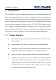
GP-L200MP User Manual Contents 1 Introduction ........................................................................................................ 1 1.1 Product Features ................................................................................... 1 1.2 Application ............................................................................................. 2 1.3 System Requirements ........................................................................... 2 1.4 Packing List ............
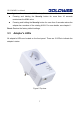
GP-L200MP User Manual 1 Introduction The GP-L200MP is a mini-PLC pass-through adapter. It can transmit data up to 200 Mbps in the household power line. It can be connected to the power socket directly without wiring. The device provides a female socket by which you can connect your terminal or power stripe directly without an outlet. The GP-L200MP adapter can enter power save mode triggered by multiple conditions.
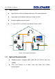
GP-L200MP User Manual 1.2 Application z High Definition (HD) and Standard Definition (SD) video distribution z Higher data rate broadband sharing for power line LAN z Shared broadband internet access z TV over IP (IPTV) and Voice over Internet Protocol (VoIP) PLC Camera Powerline WiFi Extender PLC ADSL FTTH PLC PLC Figure 1 PLC network architecture 1.
GP-L200MP User Manual RAM: At least 128MB Screen resolution: Any resolution Free disk space: At least 20MB Network interface: At least one Fast Ethernet (100 Mbps) network card, and a Ethernet Cord 1.
GP-L200MP User Manual 2 Safety Precautions This device is intended for connection to the AC power line. For installation instructions, please refer to the installation section of this user manual. The following precautions should be taken when using this product. Read all instructions before installing and operating this product. Follow all warnings and instructions marked on the product. Unplug the device from the wall outlet before cleaning. Use a damp cloth for cleaning.
GP-L200MP User Manual - If the product is exposed to rain or water - If the product does not operate normally when the operating instructions are followed - If the product exhibits a distinct change in performance 5
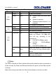
GP-L200MP User Manual 3 3.1 Getting to Know the Adapter Ethernet Interface Ethernet: The Ethernet port connects to an Ethernet network cable. The other end of the cable connects to your computer or other Ethernet-enabled network device. 3.2 Adapter's Buttons The following table describes the adapter’s buttons.
GP-L200MP User Manual Security (also referred to as the NMK button): Set the status of the device members. Pressing and holding the Security button for more than 10 seconds randomizes the NMK value. Pressing and holding the Security button for more than 3 seconds makes the adapter be a member of the existing AVLN. For more details, see chapter 6 . Reset: Restore the factory default settings. 3.3 Adapter's LEDs All adapter's LEDs are located on the front panel.
GP-L200MP User Manual The following table describes the LEDs on the device. LED Color Behavior Description Green On System runs normally. Green Blink System enters the power save mode. Power System is resetting. Password synchronization is in progress. Ethernet - Off Green On PLC adapter is powered off. Ethernet connection has established. Green Blink Data is being transmitted. - Off No Ethernet connection. Green/Red On The PLC adapter has connected to the power line network.
GP-L200MP User Manual 4 How to Install the Utility Note: Before installing the PLC utility software, make sure that there is no any other power line utility installed on your computer. If there is another utility installed, please uninstall it and restart your computer. Follow the steps below to install the utility. No password or CD-Key is needed. Step 1 Please insert the utility CD into the computer’s CD-ROM drive. Select the PLC 200AV Utility Installation folder and then double-click the setup.exe.
GP-L200MP User Manual Figure 3 Opening the setup wizard Step 2 Click Next > to show the following page.
GP-L200MP User Manual Figure 4 Selecting the folder Step 3 Click Browse… to select the installation folder, and then click Next > to continue.
GP-L200MP User Manual Figure 5 Completing the installation Step 4 Click Close to complete the installation.
GP-L200MP User Manual 5 5.1 How to Use the Utility Main Tab The Main screen provides a list of all power line devices logically connected to the computer when the utility is running. The top panel shows the local HomePlug devices connected to the network interface card (NIC) of the computer. Click Connect. The utility automatically scans the power line periodically for other HomePlug devices when it is connected to the local device.
GP-L200MP User Manual The lower panel displays all the HomePlug remote devices, which are discovered in the current logical network. The total number of remote devices connected in the same network is displayed above the remote device panel. Network type (Public or Private) depends on the network status of the local device. Autoscan shows whether the autoscan function is on. The following information is displayed for all the devices that appear in the lower panel.
GP-L200MP User Manual Figure 7 Setting the device password Step3 Click OK to verify the password. The password field accepts the device password in any case formats, with or without dash. A confirmation box appears if the password is entered correctly. If a device is not found, a message appears, providing suggestions to solve the common problems. This process might take a few seconds to get completed.
GP-L200MP User Manual the common problems. Figure 8 Adding the remote device Note: The device must be in the power line (plugged in), so that you can confirm the password and add the device to the network. If the device is not located, a warning message appears.
GP-L200MP User Manual to the power line network. By default, the utility automatically scans every a few seconds and updates the displayed information. 5.2 Privacy Tab In the Privacy screen, you can maintain security for the logical network and select the device included in the network. See Figure 9. Figure 9 Privacy tab All HomePlug devices are loaded using a default logical network (network name), which is normally “HomePlug”.
GP-L200MP User Manual If the network name changes to anything other than HomePlug, the network type in the main screen is displayed as Private. Set Local Device Only This button is used to change the network name and password of the local device. If a new network password is entered, all the devices appeared in the main panel prior to this are no longer present in the new network, effectively making the local devices not to communicate to the devices which are in the old logical network.
GP-L200MP User Manual 5.3 Diagnostics Tab The Diagnostics screen shows the system information and history of all remote devices appeared over a period of time. See Figure 10. The Upper panel shows technical data concerning software and hardware on the host computer that are used to communicate through HomePlug on the power line network.
GP-L200MP User Manual Figure 10 Diagnostics tab The Lower panel displays the history of all remote devices appeared on the computer over a certain period of time. All the devices and the parameters of the devices on the power line network are listed. Devices that are active on the current logical network show a transfer rate in the rate column. Devices on other networks, or devices that no longer exist are shown with a “?” in the rate column.
GP-L200MP User Manual HomePlug chipset manufacturer name Date device last seen on the network MAC firmware version The diagnostics information displayed can be saved to a text file for later use, or be printed for reference for a technical support call. Click Delete to delete the devices which are no longer part of the network. A dialog window pops up with a confirmation message if the user wants to delete a device whose password has been entered. 5.
GP-L200MP User Manual Preferences The lower part of the panel displays options for turning the autoscan function on or off.
GP-L200MP User Manual 6 How to Use the Security Pushbutton This section describes how to add new devices to, or remove old devices from a HomePlug AV logical network (AVLN). Both can be accomplished by using a Security (NMK) pushbutton. Operation progress and outcome can be monitored by observing the behavior of the power LED. 6.1 Forming a HomePlug AV Logical Network When two devices with different NMK values are connected to the same power line, the user wants them to form a logical network.
GP-L200MP User Manual A PLC B PLC C PLC A and B are not part of AVLN A and B want to form an AVLN Press NMK button on A less than 3 sec. Press NMK button on B less than 3 sec. A becomes “joiner” B becomes “joiner” B determines that A MAC address < B MAC address B becomes “adder” A accepts NMK from B Figure 12 Forming a HomePlug AV logical network 6.2 Joining a Network In this scenario a network exists, a new device, the ‘joiner’, wants to join the network.
GP-L200MP User Manual Figure 13 Joining a Network 6.3 Leaving a Network Suppose that a network exists. You want to remove one device, the ‘leaver’, from that network, for whatever reason, and you may want to remove the device from service altogether or have it join another logical network. Do as follows: Step1 Press the pushbutton on the ‘leaver’ for at least 10 seconds. The device will reset and restart with a random NMK. Step2 Wait for reset to complete.
GP-L200MP User Manual A PLC B PLC C PLC A, B and C form an AVLN A wants to leave the AVLN Press NMK button on A more than 10 sec.
GP-L200MP User Manual 7 How to Improve the Transmission Capacity It is important to use the PLC product complying with the following "correct rules", because it can significantly improve the transmission capacity of the network. For the PLC device without female socket, it is recommended to plug the device directly into a wall socket, not to a power stripe.
GP-L200MP User Manual Figure 16 Connecting the PLC device with the female socket 28
GP-L200MP User Manual Appendix A Specifications Chipset Intellon INT6400 Protocol HomePlug AV 1.0 Co-exists with existing HomePlug 1.
GP-L200MP User Manual Storage Temperature -20ºC to 70ºC Operating Humidity 10% to 90%, non-condensing Storage Humidity 5% to 95%, non-condensing Input Rating 100-240 VAC, 50/60Hz Certificate Compliance CE, UL, FCC Part 15 Class B Green Standard RoHS Physical Dimension L×W×H: 105mm×58mm×41mm Weight 233g 30
GP-L200MP User Manual Appendix B AVLN Acronyms and Abbreviations AV In-home Logical Network, the AVLAN is the set of STAs that possess the same network membership key. Every AVLN is managed by a single CCo.
GP-L200MP User Manual Appendix C About QoS PLC 200AV allows for 4 levels of Channel Access Priority (CAP (0 – 3)). The 8 levels of VLAN Ethernet tags must be mapped to the 4 levels of CAP priority, where CAP 3 is the highest priority and CAP 0 is the lowest. CAP 3 priority might be used for voice and network management frames, and CAP 2 is used for streaming video and music while CAP 1 and CAP 0 are used for data.
GP-L200MP User Manual The following are the factory default settings for VLAN Tags and TOS Bits: VLAN Tag Default CAP TOS Bit User Default CAP User Priority Priority Priority Priority 0 CAP1 0 CAP1 1 CAP0 1 CAP0 2 CAP0 2 CAP0 3 CAP1 3 CAP1 4 CAP2 4 CAP2 5 CAP2 5 CAP2 6 CAP3 6 CAP3 7 CAP3 7 CAP3 33
Shenzhen Landing Electronics Co.,Ltd Address: 3F Block A,BaiyingBuilding,No.1019 Nanhai Road, Nanshan District,Shenzhen,Guangdong, China Post Code:518067 E-Mail: sales@goldwebcn.com Website: http://www.goldwebcn.