
User Manual

WaveNet Radio Network 3065
Page 16
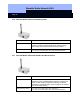
Please watch the LED while inserting the new battery. It should flash (2 times) briefly
immediately after you have placed the first
new battery into the empty battery
compartment. The node is then ready for operation (power-up reset). If the LED does
not light up, please take out the battery, short-circuit the battery contacts in the Lock
Node, then replace the battery.
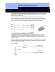
11.0 Installing WaveNet Lock Nodes
The WaveNet Lock Node should be installed at the same height from the floor as the
RF Lock. Ideally it is installed in a standard electrical box with a flush cover.
The distance from the RF Lock must be kept as small as possible, although there
should be at least 1.5 inches (3 cm) between the Lock Node and a metal door frame.
The maximum distance between the WaveNet Lock Node and the RF Lock is
approximately 14 inches (35 cm).
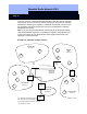
The optimum radio signal range of Router Nodes and Lock Nodes is generally
achieved by fitting the Router Nodes so that their antennas point vertically upwards or
downwards, and the Lock Nodes are fitted such that the lettering is horizontal,
enabling you to read it normally.
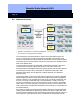
12.0 Technical specifications
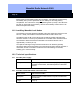
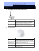
12.1 WaveNet power supply
Order number WN.POWER
Description
Externally regulated 120V AV / 6V DC plug-in power supply for
WaveNet Central Nodes, WaveNet Repeaters & WaveNet
Routers.
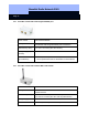
12.2 WaveNet Central Node RS232 connection cable
Order number WN.CN.RS232.CABLE
Description
RS232 connection cable between computer and WaveNet
Central Node
Length 6 ft (2 m)