
Unit installation
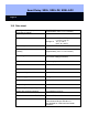

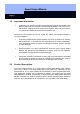

Smart Relay: SREL, SREL.ZK, SREL.ADV
Page 16
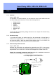
+ / ~
- / ~
NC
COM
NO
Brown
White
Green
Grey
Yellow
Batterie SREL.BAT
Netzteil
{
Relais
{
}
Externe Antenne
SREL.AV
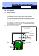
V+ F3
Evtl. Widerstand zur
Leistungsbegrenzung.
Der Ausgang V+ liefert
max. 10 mA bei 3VDC
Entweder Buzzer oder LED
Possibly resistor for restricting power
The V+ output supplies a max. 10 mA at 3 VDC
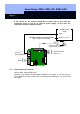
7.13 Interface
Only for SREL.ADV
For operation as a serial interface, you can select the type of card reader here that
the Smart Relay should simulate. You have the following option’s:
Wiegand 32 bit
Wiegand 26 bit
Primion
Siemens
Kaba Benzing
Gantner Legic
Isgus
You will find the corresponding cabling information in the chapter "The Smart Relay
as a Serial Interface".
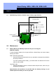
7.14 Restricted range
If you select this option, the reader range from the transponder Æ Smart Relay is
restricted from approximately 1.5 m (4.9 ft) down to 0.4 m (1.3 ft). For example, you
can use this option if there are several Smart Relays close to one another and
individual transponders are authorised for several Smart Relays.
7.15 External Beeper/ External LED
Only for SREL.ADV
Normally, the Smart Relay is configured for connection to an LED. If you want to
connect a beeper or buzzer as the external signaller, mark this option. In this way, the
beeper/buzzer can be used for an acoustic acknowledgement, instead of the LED.
Should the connected component need less than 10 m maximum current at
3 VDC, the connecting plan can look as follows: