
Unit installation

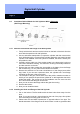
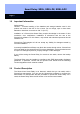
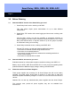

Digital Half Cylinder
Page 9
p
i
p
e
locknut
p
i
p
e
setscrews
knob
main
battery
backuo
battery
electronics
module
allen screw
flange
cable
slot
6.4 Installation Behind Blanks for Half Cylinders With 3 Setscrews
(New Flange Mounting)
6.4.1 Removal of the Knob and Flange of the Half Cylinder
1. Firmly hold the knob and remove the locknut on the back of the knob from the
knob with the special tool for half cylinders. (If the locknut is already bumping
into the profile, then start to unscrew the knob as described in the following
point (approximately one rotation) and continue).
2. Use an authorised transponder to couple the cylinder and then unscrew the
knob. While doing this, you must firmly hold the catch with your hand if the half
cylinder is not installed. If the half cylinder is installed, the catch is held by the
stop within the lock.
3. Carefully pull the cable out of the socket-contact in the electronics but do not
remove the insulation sleeving. The electronic covering is thermally welded on
and also remains on the unit.
4. Remove the two Allen screws that are parallel to the battery from the flange
with an Allen key (1.5 mm). Remove the electronics module.
5. Remove the three setscrews on the outer circumference of the flange (same
Allen key).
Note: If you can see two setscrews here, this cylinder has an old flange
mounting (in this case, refer to Point 6.5).
6. Remove the flange and locknut.
7. Now you can install the blank.