
Unit installation


VdS Shunt lock function 3066
Page 8
+
8
...16V
Masse
+LED
- LED
C
NC
N0
SAB0
SAB0
SAB0
SAB0
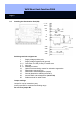
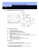
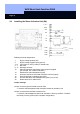
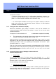
2.2 Installing the Deactivation Unit (DA)
Soldering terminal assignments:
1 Supply voltage positive pole
2 Supply voltage negative pole (ground)
3 + 4 Connection for LED (5 volts) in outside area
5 - 7 Not used
8 - 11 Sabotage contacts
12 Optional lock monitoring contact for activation suppression
13 Deactivation request (input)
14 Deactivation acknowledgement (output)
15 Ground (identical to soldering terminal 2)
29 Acoustic BAC acknowledgement
(not for DA)
30 Solder terminal for cable screen
Jumper settings:
Jumper B1 can be inserted any way
Insert jumper B2 for maximum transmitting range
Do not insert jumper B3