
Unit installation


VdS Shunt lock function 3066
Page 7
2.0 Assembly Instructions
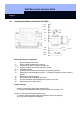
2.1 General Information on Installing the Components
Always install in the protected area, for example, in the inside area behind the door,
behind brickwork, etc. There are some materials, however, such as stainless steel or
aluminum, that can significantly reduce the range. There may also be sources of
magnetic interference near the activation or deactivation unit that also very strongly
reduce the range. When making the connections, please observe the technical
specifications for the activation unit and the relay (refer to Chap. 6). Failing to comply
with these values can lead to interference with the function of the components or
even to destruction of the components. Make absolutely sure that the polarity is
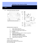
correct. You can attach the components (deactivation and activation units) on the
wall surface with two countersunk head screws, 3.5 x 30 mm, and two S5 plastic
plugs (not included in the delivery).
The two enclosed VdS adhesive labels guarantee permanent evidence if the housing
is opened without authorization (sealing of the cover screws).
Programming the components
Program the Shunt lock components and accompanying lockings before installation.
When doing this, please keep the following points in mind:
• Program activation units, deactivation units and locking cylinders in the same
locking plan
• Select type Control unit for the shunt lock components
• During programming, supply only one component with power at a time and do
not connect the cables to one another.
• After programming, read out the components and verify that they report
correctly.
Refer to Chapter 3 for more detailed information.
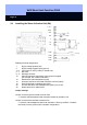
Installing a locking that should be deactivated with the Shunt lock function
Install the digital locking (Smart Relay or locking cylinder) that should be deactivated
by the Shunt lock function. Follow the installation guidelines. These are under the
relevant heading in the system manual.