Manual 3060 System Version: September 2006 If the contents of the foreign language version of the documentation differ from the contents of the original German version, the original German version shall apply in case of doubt. We reserve the right to make technical changes. SimonsVoss Technologies AG • Feringastraße 4 • 85774 Unterföhring • Germany Hotline 01805-SV3060 • FAQs www.simons-voss.
Table of Contents Version: June 2006
Table of Contents Seite 2 P People to Contact Sales Technical Address in Munich D Digital Locking System 3060 General method of operation The components Access control, time zone administration V Digital Locking Cylinder 3061 VdS Method of operation Installation instructions Battery warning, battery replacement H Digital Half Cylinder 3061 Method of operation Installation instructions Battery warning, battery replacement R Digital Smart Relay 3063 Installation Connections Programming Smart Output
Table of Contents Seite 3 Q Biometric Transponder Q 3007 Method of operation Learn state Recognize state Delete state PinCode Keypad 3068 Method of operation Installation Programming N Network 3065 B Shunt lock function 3066 Activation unit Deactivation unit Installation and connecting plan E Shunt lock function 3066 VdS Master activation unit Slave activation Unit Deactivation Unit VdS-compliant Installation M Programming Transponder 3067 Backup card Error messages Programming P PalmCD Commiss
Table of Contents Seite 4 K Key Explanation of technical terms Special Symbols
People to contact Version: September 2006
People to contact Page 2 SALES If you have any questions please contact our specialist dealers, or the sales representative responsible for your region. You can obtain information concerning the responsible contact at the following telephone number. +49 89-9 92 28-180 United Kingdom SimonsVoss Technologies Ltd. Mr. Oliver Quaisser 44 Newton Court, Old Windsor Berkshire SL4 2SN Great Britain Tel. +44 / (0)1753 / 85 98 44 Fax +44 / (0)1753 / 83 17 03 Email: oliver.quaisser@simons-voss.co.
Digital Locking System 3060 State of: June 2006
Digital Locking System 3060 Register 1.0 General Method of Operation ___________________________3 2.0 The Components of the Digital Locking and ________________ Organization System 3060______________________________3 3.0 2.1 Software LDB ___________________________________________ 3 2.2 Programming ___________________________________________ 4 2.3 Digital Locking Cylinder 3061 ______________________________ 4 2.4 Digital Smart Relay 3063 __________________________________ 4 2.
Digital Locking System 3060 Page 3 1.0 General Method of Operation The Digital Locking and Organization System 3060 is modularly constructed and is suitable for uses ranging from a simple locking system for individual doors all the way to a complex PC-controlled access control system. Conventional mechanical keys are replaced by the programmable transponder, which controls doors, gates, barriers, furniture and elevators, for example, over radio transmission.
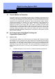
Digital Locking System 3060 Page 4 2.2 Programming You will need the SmartCD and a PDA for programming the digital components. The data is encoded and then transmitted to the digital components via radio signal. Another possibility for programming a Digital Locking Cylinder 3061 and Transponder 3064 is with the Programming Transponder 3067. For example, you can issue or change access authorizations in small systems by simply pressing a button when you lose a key or change the locking plan.
Digital Locking System 3060 Page 5 cylinder, Smart Relay or activation unit. 2.6 Network 3065 The cable-free Network 3065 is an online access control system that administers, visualises and archives all System 3060 information in one central location, and all without manipulations at the door, door frame or the door hardware. It is especially recommended for medium-sized and large locking systems in order to be able to configure and administer the locking system from a central PC.
Digital Locking System 3060 Page 6 After the access list has been read out with the programming device or network nodes, it is imported into the PC and administered there by the locking plan software. A total of 10,000 accesses can be stored in the PC file. When the data is accepted from the programming device, a comparison is done so that it is always only the current, new accesses that are accepted into the PC file. 3.
Digital Locking Cylinder 3061 VdS State of: September 2006
Digital Locking Cylinder 3061 VdS Page 2 1.0 2.0 3.0 4.0 Method of Operation __________________________________3 1.1 General Information ______________________________________ 3 1.2 Opening and Locking From Outside_________________________ 3 1.3 Opening and Locking From Inside __________________________ 3 Special Models _______________________________________4 2.1 FH Version ______________________________________________ 4 2.
Digital Locking Cylinder 3061 VdS Page 3 1.0 Method of Operation 1.1 General Information The Digital Locking Cylinder 3061 VdS meets the requirements of VdS (Association of German Property Insurers) Class B and its outer dimensions exactly match those of a standard mechanical cylinder. In comparison to mechanical systems, it excels because it is very easy to install, provides greater security, is more flexible and costs less to operate.
Digital Locking Cylinder 3061 VdS Page 4 2.0 Special Models The standard Digital Locking Cylinder 3061 VdS is equipped as a TZC version, which means that the following functions are always included: Access logging The locking cylinder stores the last 128 accesses with date, time and the user name of the transponder. You can read out the data with the PalmCD2 or over the network.
Digital Locking Cylinder 3061 VdS Page 5 3.3 Logging Unauthorised Access Attempts For cylinder version 10.2 and later and in combination with the LDG Version 1.40, it is possible to log unauthorised access attempts, as well as authorised accesses. This includes both access attempts without authorisation and access attempts outside the specified time zone.
Digital Locking Cylinder 3061 VdS Page 6 4.2 Transponder If the transponder battery voltage is coming to an end, eight short signal tones, coming quickly one after another, sound each time the transponder is operated on the locking cylinder after the uncoupling. & 5.0 Attention: Do not take out the transponder battery because this will probably result in the loss of data. See the “Transponder 3064” manual for more information.
Digital Locking Cylinder 3061 VdS Page 7 Fix the lock nut in position with the special tool and press it against the flange. Now turn the inner knob onto the screw thread until the stop and tighten the locknut firmly. Now operate an authorised transponder and test the function. & Please dispose of discharged lithium batteries immediately. Store away from children, do not open and do not throw into fire.
Digital Locking Cylinder 3061 VdS Page 8 6.4 Inserting the Digital Cylinder Into the Lock First turn the lock pin until it is pointing straight down. Then insert the Digital Locking Cylinder through the lock so that the inner knob (long knob) points toward the inside of the door. Fasten the cylinder with the lock screw included in the delivery Never hit against the knobs during installation. Do not bring the cylinder into contact with oil, paint or acid. 6.
Digital Locking Cylinder 3061 VdS Page 9 8.0 Data Sheet Knobs Material Colours Diameter FH cylinder knobs Material Colour Diameter Stainless steel Brushed stainless steel Brass 30 mm Outer knob stainless steel, inner knob plastic Black 30 mm Profile cylinders Standard length Construction length Outside 30 mm, inside 30 mm In 5 mm increments (no kit) up to a total length of 140 mm, where one side of the cylinder can have a max. length of 90 mm. Other lengths upon request. Battery Type Lithium 3.
Digital Half Cylinder 3061 State of: September 2006
Digital Half Cylinder 3061 Content 1.0 2.0 Method of Operation __________________________________4 1.1 General Information ______________________________________ 4 1.2 Opening and Locking _____________________________________ 4 Special Models _______________________________________4 2.1 3.0 4.0 5.0 PLUS Version ___________________________________________ 4 Additional Functions __________________________________5 3.1 OMRON ________________________________________________ 5 3.
Digital Half Cylinder 3061 Content 6.0 Installation Instructions________________________________8 6.1 General Information ______________________________________ 8 6.2 Programming a Half Cylinder ______________________________ 8 6.3 Installing in Doors _______________________________________ 8 6.4 Installation Behind Blanks for Half Cylinders With 3 Setscrews __ 9 (New Flange Mounting) _________________________________________ 9 6.4.
Digital Half Cylinder Page 4 1.0 Method of Operation 1.0 General Information The outer dimensions of the Digital Half Cylinder exactly match those of a mechanical cylinder complying with DIN 18252. Please ask for approved self-locking and antipanic locks at the manufacturer. 1.1 Opening and Locking When not activated, the outer knob turns freely. It is not possible to open the door or to lock it.
Digital Half Cylinder Page 5 3.0 Additional Functions 3.1 OMRON All product versions can be operated in OMRON mode. You will find a detailed description in the Smart Relay manual. 3.2 Extending the Coupling Time The default time for the coupling of the cylinder is approximately 5 seconds. You can use the software to extend this time to approximately 10 seconds. This shortens the lifetime of the battery, however. 3.3 Logging Unauthorised Access Attempts For cylinder version 10.
Digital Half Cylinder Page 6 4.0 Battery Warnings 4.1 Half Cylinder Warning level 1 for main battery If the main battery of the half cylinder goes empty, eight short signal tones, coming quickly one after another, sound after you operate the transponder and before the cylinder couples. You must replace both batteries now. Warning level 2 for backup battery (SW Version 10.0 & SW Version 10.
Digital Half Cylinder Page 7 5.0 Battery Replacement Only authorised personnel are permitted to replace the battery. Use only batteries that are supplied by SimonsVoss. 1. Firmly hold the knob and remove the locknut on the back of the knob from the knob with the special tool for half cylinders. 2. Use an authorised transponder to couple the cylinder and unscrew the knob by turning it counter-clockwise. While doing this, you must firmly hold the catch with your hand if the half cylinder is not installed.
Digital Half Cylinder Page 8 6.0 Installation Instructions 6.1 General Information Only trained and authorised personnel are permitted to perform the installation. The battery used in the cylinder can present a risk of fire and burns if not handled correctly! Do not charge, open, heat to more than 100° C (212° F) or burn! Do not short-circuit! When installing the digital half cylinder, make sure that there are no sources of interference in the vicinity. You should install half cylinders at least 0.
Digital Half Cylinder Page 9 6.4 Installation Behind Blanks for Half Cylinders With 3 Setscrews (New Flange Mounting) pipe locknut pipe setscrews main battery backuo battery knob slot cable flange allen screw electronics module 6.4.1 Removal of the Knob and Flange of the Half Cylinder 1. Firmly hold the knob and remove the locknut on the back of the knob from the knob with the special tool for half cylinders.
Digital Half Cylinder Page 10 6.4.2 Installing the Knob and Flange of the Half Cylinder 1. Put on the locknut. The flat surface with the bore holes faces away from the cylinder. Note: If you cannot see any screw thread on the end of the pipe, this cylinder has a new flange mounting (in this case, refer to Point 6.4). 2. Put the flange onto the end of the pipe; the side of the flange with the screw thread faces away from the cylinder. The flange contains a crosspin that sticks out of the interior diameter.
Digital Half Cylinder Page 11 6.5 Installation Behind Blanks for Half Cylinders With 2 Setscrews (Old Flange Mounting) locknut flange electronics module pipe knob slot for positioning of the special tool setscrew 6.5.1 Removal of the Knob and Flange of the Half Cylinder 1. Firmly hold the knob and remove the locknut on the back of the knob from the knob with the special tool for half cylinders. 2. Use an authorised transponder to couple the cylinder and then unscrew the knob.
Digital Half Cylinder Page 12 3. 4. 5. 6. 7. 8. 6.6 the flange holds securely. To find the exact position quickly, the flat surfaces of the pipe and flange have black markings that must line up. Put the flange on the end of the pipe without screwing it in. The side with the small outside diameter points towards the door. The fore-part of the pipe, which sticks out of the profile, contains two slots in which you can position the special tool (offset 90° to the lengthwise slot which guides the cable).
Digital Half Cylinder Page 13 7.0 Data Sheet Dimensions Standard length Standard length Multirast (MR) Max. profile length Knob diameter Knob length Standard for profile dimensions Battery Batteries Service life Environmental Conditions Operating temperature range Storage temperature range Degree of protection 30/10 mm 30/15 mm 100 mm (in 5mm intervals) 33,5 x 30 mm 51.5 mm (distance from knob end to profile fore-part) DIN 18252 Lithium, 3.
Smart Relay: SREL, SREL.ZK, SREL.
Smart Relay: SREL, SREL.ZK, SREL.ADV Content 1.0 Important Information _________________________________4 2.0 Product Description ___________________________________4 3.0 Before Ordering ______________________________________5 4.0 3.1 Determine Which Version of the Smart Relay you need_________ 5 3.2 Determine Which Accessories you need _____________________ 5 3.3 Dimension and Procure Power Supplies _____________________ 5 3.
Smart Relay: SREL, SREL.ZK, SREL.ADV Content 8.0 9.0 7.11 Number of expansion modules ____________________________ 15 7.12 Pulse length ___________________________________________ 15 7.13 Interface _______________________________________________ 16 7.14 Restricted range ________________________________________ 16 7.15 External Beeper/ External LED ____________________________ 16 7.
Smart Relay: SREL, SREL.ZK, SREL.ADV Page 4 1.0 Important Information Safety remark: Caution! – Incorrect handling of the batteries and storage batteries used in this product can result in the risk of fire or burns. Do not charge, open or burn these batteries or heat them to more than 100 °C (212 °F). Installation of a SimonsVoss Smart Relay requires knowledge in the areas of door mechanics, door certifications, installation of electronics and the use of the SimonsVoss software.
Smart Relay: SREL, SREL.ZK, SREL.ADV Page 5 3.0 Before Ordering 3.1 Determine Which Version of the Smart Relay you need 1. Smart Relay basic version: ordering code SREL This relay allows simple yes/no authorisation for up to 8184 different transponders. 2. Smart Relay TZC version with access logging and time zones: ordering code SREL.ZK. Like the basic version, but with the capability of separately switching on access logging for the last 1024 accesses (for firmware version 4.0.01.
Smart Relay: SREL, SREL.ZK, SREL.ADV Page 6 3.4 Determine the Installation Position The range from the transponder to the Smart Relay (reader range) is a maximum of 1.5 m (5 feet), but can be dampened by a metal environment (particularly by strong magnetic fields or aluminium). Ideally, you should conduct a range test with an authorised transponder and a battery-operated Smart Relay. 3.5 4.0 Additional Information: - All cables for connecting to the Smart Relay should be type IY(ST)Y ....x0.
Smart Relay: SREL, SREL.ZK, SREL.ADV Page 7 Installation of the Backup battery Backup Batterie das the Smart Relais Insert the battery nur only einsetzen, if you will bewenn operating Smart Relaymit with Netzteil bei Betrieb mit ifSREL.BAT diese the powerbetrieben supply. Dowird, not insert this battery you will be operating with nicht the SREL.BAT! Batterie einsetzen! SREL SREL and SREL.ZK und SREL.ZK +/~ -/~ C A B +V F3 F2 F1 SREL.
Smart Relay: SREL, SREL.ZK, SREL.ADV Page 8 5.0 Installation Switch off the supply voltage (if necessary, pull out the plug or disconnect the battery). Connect all cables to the terminals provided on the Smart Relay (see Connection Assignments on the following page) If you are connecting a direct current power supply, make sure that you get the polarity right.
Smart Relay: SREL, SREL.ZK, SREL.ADV Page 9 6.0 Connection Assignments 6.1 SREL and SREL.ZK Power Netzteil { +- // ~~ Battery Batterie SREL.BAT Relais Re- { Antenna NC COM NO 1 RS 485-COM 2 RS 485-A 3 RS 485-B 4 + Vaux (3...5 V) 5 LED / Buzzer / Input 1 / CLS 6 Seriell 1 / Input 2 7 Seriell 2 Externe Einund external inputs Ausgänge and outputs +/~ Power Netzteil supply { -/~ Battery SREL.
Smart Relay: SREL, SREL.ZK, SREL.ADV Page 10 6.2 SREL.ADV 6.3 Description of the SREL, SREL.ZK and SREL.
Smart Relay: SREL, SREL.ZK, SREL.ADV Page 11 7.0 Programming and Configuration When you choose Smart Relay as the locking type in the SimonsVoss software (Version 1.
Smart Relay: SREL, SREL.ZK, SREL.ADV Page 12 7.1 Access control Only possible for SREL.ZK and SREL.ADV The last 1024 transponder activation’s are saved with the date and time. 7.2 Time zone control Only possible for SREL.ZK and SREL.ADV You can load a time zone plan and the transponders are then approved or blocked, according to their time zone group. 7.3 Overlay Replacement transponders can overwrite the transponders that they replace.
Smart Relay: SREL, SREL.ZK, SREL.ADV Page 13 1. Manual locking: The door is not locked automatically according to the selected time of day, but instead only after an authorised transponder is operated after this time. 2. Automatic locking (default setting): The door is locked at exactly the time stored in the time zone plan. 3.
Smart Relay: SREL, SREL.ZK, SREL.ADV Page 14 7.7.1 The Smart Relay in OMRON Mode Authorized? Access control system Externes Zutrittskontrolloder External access control or Zeiterfassungssystem time recording system GND Release relay Freischalt Relais + 5..12VDC 1K 1K 1K Pull Up up Widerstände Pull resistors CLS Clock / D1 Data / D0 Power Netzteil { +- // ~~ F3 F2 F1 Battery SREL.BAT Batterie SREL.
Smart Relay: SREL, SREL.ZK, SREL.ADV Page 15 7.8 No acoustic programmer acknowledge Only SREL.ADV Mark this field if you want no programmer acknowledge to be given via a connected buzzer/beeper when the Smart Relay is programmed. 7.9 External beeper/ External LED Only SREL.ADV This is where you specify which external unit is connected.
Smart Relay: SREL, SREL.ZK, SREL.ADV Page 16 7.13 Interface Only for SREL.ADV For operation as a serial interface, you can select the type of card reader here that the Smart Relay should simulate. You have the following option’s: Wiegand 32 bit Wiegand 26 bit Primion Siemens Kaba Benzing Gantner Legic Isgus You will find the corresponding cabling information in the chapter "The Smart Relay as a Serial Interface". 7.
Smart Relay: SREL, SREL.ZK, SREL.ADV Page 17 If the current for the external component is larger than 10 mA, then this component must be fed by an external power supply. In this case, the connection should be made as follows: Ext. Netzteil External power supply GND Evtl. W iderstand zur Possibly resistor for restricting power Leistungsbegrenzung. The F3 Der output is max. 50 mA. Ausgang F3 verträgt Maximal + 24V max.
Smart Relay: SREL, SREL.ZK, SREL.ADV External access control or time recording system Page 18 8.0 Serial Interface 8.1 Functional Description In order to use a Smart Relay as a card reader in an external access control or time recording system, both the hardware (cable and signal level) and the data formats must correspond exactly to those of the card reader. Only then can the external system understand and evaluate the data from the SimonsVoss transponders.
Smart Relay: SREL, SREL.ZK, SREL.ADV Page 19 8.3 Kaba Benzing, Siemens, Gantner Legic, Primion, Isgus Interface Externes External access Zutrittskontrollcontrol oroder time recording system Zeiterfassungssystem GND + 5..12VDC 1K 1K 1K Pull-up resistors Pull Up Widerstände CLS Clock Data +/~ Power supply Netzteil { F2 F1 -/~ Batterie SREL.BAT Battery SREL.BAT Relay Relais { Brown White Green Grey Yellow } Externe ExternalAntenne antenna SREL.AV SREL.AV NC COM NO 9.0 Maintenance 9.
Smart Relay: SREL, SREL.ZK, SREL.ADV Page 20 9.2 Backup Battery A discharged backup battery can cause the internal clock in the type SREL.ZK or SREL.ADV Smart Relay to stop. For this reason, we recommend that you check the time of day at routine intervals. A backup battery will last approximately 10 years if there is no power supply interruption. If the Smart Relay needs the backup battery often because of frequent power failures, you should replace this battery routinely.
Smart Relay: SREL, SREL.ZK, SREL.ADV Page 21 10.0 Data sheet Housing made of black plastic: Dimensions [LxWxH] Degree of protection 72 x 57 x 25.5 mm (approximately 2.8 x 2.2 x 1.0 inches) IP 20, not tested for outside use Temperature Air humidity Operation at: -22°C to +55°C (-31°F to +131°F) Storage at: 0°C to +40°C (32°F to +104°F) <95% without moisture condensation Printed circuit board dimensions [LxWxH] 50 x 50 x 14 mm (approximately 2.0 x 2.0 x 0.
Smart Output Module State of: June 2006
Smart Output Module Content 1.0 Important Information _________________________________4 2.0 Product Description ___________________________________4 3.0 Before Ordering ______________________________________5 3.1 Smart Relay _____________________________________________ 5 3.2 Determine the Number of Modules that are Needed ____________ 5 3.3 Obtain and Dimension the Power Supply ____________________ 5 3.4 Determine the Installation Technique and the Installation Site ___ 5 3.
Smart Output Module Content 9.0 Meaning of the LEDs _________________________________15 9.1 LEDs for Each Output ___________________________________ 15 9.2 State LED ______________________________________________ 15 10.
Smart Output Module Page 4 1.0 Important Information Installation of a SimonsVoss Smart Output Module requires knowledge in the areas of approvals for electronic and electrical installation and in the use of SimonsVoss software and the SimonsVoss System 3060. For this reason, only trained and expert personnel should install the unit. SimonsVoss Technologies AG will not accept any liability for damages caused by incorrect installation. 2.
Smart Output Module Page 5 3.0 Before Ordering 3.1 Smart Relay At least one type SREL.ADV Smart Relay is necessary for operating a Smart Output Module. Please read the Smart Relay Product Manual for information on ordering. 3.2 Determine the Number of Modules that are Needed 3.3 Up to 16 external modules can be connected to one type SREL.ADV Smart Relay. If you select the "Signalling" option in the configuration, the number of outputs per Smart Output Module is reduced from eight to four.
Smart Output Module Page 6 4.0 5.0 Before Installation Unpack the Smart Output Module and inspect it for external damages. Connect the Smart Output Module to a type SREL.ADV Smart Relay (see Connection to the Smart Relay) and provide both units with voltage over the power supply. Note the polarity. Activate the Smart Relay with a transponder in the condition as received from the factory.
Smart Output Module Page 7 6.0 Connections 6.1 Terminal Assignments Bus connection Busanschluß To type SREL.ADV zum Smart Relais Typ Smart Relay SREL.ADV Outputs Ausgänge / Outputs I-I-/ /I+I+Not used Nicht belegt OutputOutput -wenn die Versorgungsspannung unter This output switches 10,5 V +/-0,5V absinkt schaltet dieser off when the supply Ausgang aus. voltage falls below Out| I-|I+| B | A | C |4a|4b|3a|3b|2a|2b|1a|1b 10.5 V +/-0.
Smart Output Module Page 8 6.2 Connection Assignments Name Output Symbol Out Isolated digital input II+ Bus connection to the A type SREL.ADV B Smart Relay C Outputs 1a 1b 2a 2b 3a 3b 4a 4b Outputs or 5a connections for 5b signalling 6a 6b 7a 7b 8a 8b Name Ground Description If the supply voltage falls below 10.0 VDC +/- 0.5V, this output switches off. Typically, this output is connected to A-, if it is necessary to switch the AUX relay before the switching functions fail.
+/~ -/~ |A-|K1|A+| +|K2|8a|8b|7a|7b|6a|6b|5a|5b Out| I-|I+| A | B | C |4a|4b|3a|3b|2a|2b|1a|1b 7.
Smart Output Module Page 10 Standard Power Supply Connection 7.2 |A-|K1|A+| +|K2|8a|8b|7a|7b|6a|6b|5a|5b Out| I-|I+| B | A | C |4a|4b|3a|3b|2a|2b|1a|1b 7.1 Netzteil Power supply + - Emergency Release Connection for a Fire Alarm System When the fire alarm system relay opens, the Smart Output Module supply voltage is stopped, consequently closing outputs 1 to 8.
Smart Output Module Page 11 7.3 Protective Circuit to Prevent an Opening when the Supply Voltage Fails When the supply voltage range falls below the acceptable level, the actuator supply over the AUX relay is interrupted. The switching output (OUT) is used in this connection.
Smart Output Module Page 12 7.4 Protective Circuit for the Signaling Option Outputs Each pair of terminals opposite one another (1 and 5, 2 and 6, 3 and 7, 4 and 8) works together. When the lower output in the module is switched, the corresponding assigned output blinks.
Smart Output Module Page 13 8.0 Programming and Configuration 8.1 General Information To program the Smart Output Module, connect it to a type SREL.ADV Smart Relay. Supply power to both the Smart Relay and the Smart Output Module and hold the programming device close to the Smart Relay. The Smart Output Module itself cannot communicate with the Config Device. 8.2 Enter the Number of Modules Enter the number of connected Smart Output Modules in the Smart Relay configuration.
Smart Output Module Page 14 8.4 Adjust the Pulse Length The modules appear in the locking plan as the locking type "expansion module". You can select a pulse length from 0.1 to 25.5 seconds in the configuration for each module. This length then applies to all of the module's outputs. 8.5 Select Signaling Signaling is a special function where two of a module's outputs always work together.
Smart Output Module Page 15 9.0 Meaning of the LEDs 9.1 LEDs for Each Output Each of the 8 outputs has an LED assigned to it. This LED displays the state of the output. Green -> output closed Off -> output open 9.2 State LED In addition, there is a three-color LED that displays the state of the Smart Output Module: Lights green every 5 seconds Æ Communication with the Smart Relay is OK Lights red every 5 seconds Æ Communication with the Smart Relay is dis rupted.
Smart Output Module Page 16 10.0 Technical Specifications Housing made of plastic with transparent cover for mounting on DIN rail. Weight Degree of protection Ambient temperature Air humidity Supply voltage Power limit Quiescent current Max.
Transponder 3064 State of: September 2006
Transponder 3064 Content 1.0 2.0 3.0 4.0 5.0 6.0 7.0 Method of Operation __________________________________3 1.1 General ________________________________________________ 3 1.2 Higher Priority Locking Level ______________________________ 4 Special Models _______________________________________5 2.1 Password Transponder ___________________________________ 5 2.2 Switching Transponder ___________________________________ 5 2.
Transponder 3064 Page 3 1.0 Method of Operation 1.1 General The Transponder 3064 is a digital “key” that is programmed with the locking plan software and that works over radio transmission with no physical contact. All functions, for example, opening and closing doors, gates, barriers, furniture locks, etc., are carried out by pressing a button.
Transponder 3064 Page 4 1.2 Higher Priority Locking Level If it is necessary to have transponders that are authorised for more than 3 mutually independent locking systems, “higher priority locking levels” must be set up in these locking systems. There are a maximum of 3 higher priority locking levels available for this. All transponders of a higher priority locking level have the same authorisation. One digital locking distinguishes between a maximum of three higher priority levels.
Transponder 3064 Page 5 2.0 Special Models 2.1 Password Transponder Instead of manually entering the locking system password, you can transmit it over radio frequency with the help of a special transponder. Standard transponders cannot be used as password transponders. 2.2 Switching Transponder With this transponder, a two-wire cable (approx. 1m or 37 inches) is connected to the switch contacts of the button and guided outside the device.
Transponder 3064 Page 6 Explosion Protection Transponder 2.7 General Information This special product is a transponder that is permitted to be carried into and used in areas subject to explosion hazards, called Zone 1. An area is denoted as Zone 1 when atmospheres capable of exploding occur occasionally. It is crucial that you keep in mind the following issues: • • 3.2 You are not permitted to open the housing.
Transponder 3064 Page 7 3.0 Additional Functions The following functions can be activated in the locking plan software: 3.1 Time Zone Control For TZC version digital lockings, you can program transponders that have locking authorisation for specific times only. These time zones are deposited in the locking plan software, and the transponders are then assigned to an appropriate time zone group. Example: 3.2 Mr. Miller receives the following authorisation: Monday to Friday from 9:00 am, until 6:30 p.m.
Transponder 3064 Page 8 4.0 Battery Replacement 4.1 Battery Replacement 3064 If a battery warning occurs, then the transponder battery can be changed at any time (see the Manual on the 3061 Locking Cylinder – Battery warning). Open the casing carefully so that you can see the battery. Open the battery clip and remove the battery, insert a new one, and close the clip. Press the casing back together again.
Transponder 3064 Page 9 6.0 Data Sheet Housing • • • • • • • • Made of weather-resistant plastic Colour: Black Degree of protection: IP 65 Diameter: 42 mm Integrated lithium battery Max. 1,000,000 operations, or 10 years standby Access authorisations for up to 48.
Q3007 Biometric Transponder State of: September 2006
Q3007 Biometric Transponder Content 1.0 2.0 General Instructions __________________________________3 1.1 Safety instructions _______________________________________ 3 1.2 Product description ______________________________________ 3 Overview of function __________________________________4 2.1 Basic information on operation_____________________________ 4 2.2 Operating states _________________________________________ 4 2.3 How the transponder works _______________________________ 5 2.
Q3007 Biometric Transponder Page 3 1.0 General Instructions Please take 15 minutes to familiarise yourself with how your Biometric Transponder Q3007 works with the help of these operating instructions. 1.1 Safety instructions Caution! – The batteries used in this product could burn or cause a fire if they are not handled properly. Do not charge, open or burn these batteries or heat to over 100°C. Make sure that the sensor surface is not dirty or scratched.
Q3007 Biometric Transponder Page 4 2.0 Overview of function 2.1 Basic information on operation The Biometric Transponder Q3007 scans fingerprints using a fingerprint sensor. The finger is dragged across the sensor, rather than being pressed against it. The following should be noted: The fingerprint to be scanned/ memorised should always be dragged over the sensor in the same way.
Q3007 Biometric Transponder Page 5 2.3 How the transponder works Stand-by mode: LED not illuminated Briefly press button once, then release Recognise mode: LED flashes green Press button and hold down for 3 sec. Drag finger across sensor Transponder triggered Learn mode: LED flashes yellow Press button and hold down for 3 sec. Drag Administrator finger once over sensor and new finger (User finger) 3 times over sensor.
Q3007 Biometric Transponder Page 6 Please note: The first two fingerprints to be scanned in are automatically (!) the Administrator fingerprints. Without them, no further fingerprints can be scanned in or deleted later! To scan in and store the first Administrator fingerprint (e.g. left thumb), please do the following: 1. Briefly press the transponder button; the LED will flash green. 2. Then press the button again and hold it pressed for at least 3 seconds (until the LED flashes yellow). 3.
Q3007 Biometric Transponder Page 7 Further fingerprints (maximum 4) can be scanned in as the Administrator fingerprints have been, except that the Q3007 must first be cleared for this by an Administrator fingerprint. This prevents unauthorised persons from scanning in their own fingerprints and thus gaining access rights that are not allowed. We recommend that every person who is to use the Q3007 should also be scanned in with two fingerprints, one per hand.
Q3007 Biometric Transponder Page 8 6. Now repeat step 4 twice again (so that you have drawn your finger three times across the fingerprint sensor altogether). If an attempt has been unsuccessful (LED is illuminated red), drag your finger across the sensor again. Once the fingerprint has successfully been scanned, the data are saved. This step takes about 2-5 seconds and is indicated by a yellow flashing light at 2 second intervals.
Q3007 Biometric Transponder Page 9 2.6 "Recognise" mode: one-off triggering of transponder The mode known as the Recognise mode is the normal operating state for the Q3007, i.e. a person whose fingerprint has been scanned in would like to trigger a Transponder signal, e.g. to open a door with a digital locking cylinder or to programme the Transponder within a locking plan. To do this, proceed as follows: 1. Press the button of the Q3007 briefly (for around 0.5 sec.), and the LED will then flash green. 2.
Q3007 Biometric Transponder Page 10 3.0 "Delete" mode: deleting fingerprints Both individually scanned fingerprints and all the fingerprints can be deleted from the memory. If normal fingerprints (not Administrator fingerprints) are deleted, the other fingers that have been scanned in are not deleted. No Administrator fingerprint is needed to do this (any normal user can delete his own fingerprint). If one of the two Administrator fingerprints is deleted, all the fingerprints are automatically deleted.
Q3007 Biometric Transponder Page 11 To enter Transparent mode, please proceed as follows: 1. Press and hold the transponder button (longer than 1.5 seconds, < 3 sec.). The LED will flash green rapidly. The Transponder will now react to the button as if it were in Recognise mode. 2. Drag finger across sensor (LED shows green if the fingerprint is recognised). 3. The Biometric Transponder is triggered and switches to Transparent mode. The LED flashes red. 4.
Q3007 Biometric Transponder Page 12 7.0 Technical Data Dimensions: H x W x D 65 x 32 x18 mm Weight 22 g Colour Grey, with blue button Operating distance, locking cylinders approx. 40 cm (if the transponder (lengthways) is held parallel with the cylinder antenna) Operating Smart Relay approx.
Q3007 Biometric Transponder Page 13 8.0 Table of Diode Signals LED Mode off Standby off moving finger on sensor followed by comparison with scanned fingerprint, please wait (max. 4 seconds) Slow green flashing light Recognise mode, wait for finger (max. 30 seconds) Fast green flashing light Release for transparent mode, wait for finger (max.
PinCode Keypad 3068 State of : September 2006
PinCode Keypad 3068 Content 1.0 2.0 General information 4 1.1 Safety Remarks __________________________________________ 4 1.2 Product Description _______________________________________ 5 Functional Overview 5 2.1 Function Overview ________________________________________ 5 2.2 Operating modes _________________________________________ 6 2.3 Operating _______________________________________________ 6 3.0 Start-up 7 4.0 Programming PINs 8 5.0 6.0 7.0 8.0 9.0 4.
PinCode Keypad 3068 Content 13.0 Special Functions 17 13.1 Hidden Lock for SimonsVoss VdS Shuntlock 3066 ______________ 17 13.2 Miscellaneous ___________________________________________ 18 14.
PinCode Keypad 3068 Page 4 1.0. General information Please take 15 minutes and read through these Instructions in order to familiarise yourself with the function of your PinCode Keypad.. 1.1 Safety Remarks Caution! Incorrect handling of the batteries used in this product can result in the risk of fire or burns. Do not charge, open or burn these batteries or heat them to more than 100° C (212° F).
PinCode Keypad 3068 Page 5 1.2 Product Description The PinCode Keypad 3068 is a digital "key" (transponder), which opens SimonsVoss lockings without contact via radio transmission after the correct numerical codes are entered. To configure the system, you must first correctly configure at least one PIN and the associated integrated transponder for the locking. The associated locking is then released after a correct PIN has been entered.
PinCode Keypad 3068 Page 6 2.2 Operating modes The PinCode Keypad has four distinct operating modes: Mode: Explanation: Standby The PIN Code Keypad is in standby mode, and uses only very little power. Opening After a correct PIN has been entered, the locking is addressed via radio transmission and can be operated. Programming In this mode, the following can be programmed or reset: Battery warning 2.3 • the individual PINs (max.
PinCode Keypad 3068 Page 7 3.0 Start-up The first time the system is started up, you will need to replace the factory-set master PIN: 12345678 with your own master PIN. Requirement: • • 8 digits may not start with a "0" Your personal master PIN is needed for all programming processes for authentication purposes. Please keep it in a safe place where it cannot be accessed by unauthorised persons.
PinCode Keypad 3068 Page 8 4.0 Programming PINs The Master PIN required for all programming procedures is defined by the user (e.g. the System Administrator). Please keep it safe and inaccessible to unauthorised persons, since the Master PIN is required for all programming procedures. 4.1 First Start-up For the first start-up, the safety of your locking system requires that you program at least one PIN.
PinCode Keypad 3068 Page 9 4.3 Procedure Input "0" Input "master PIN" Input "1 (for PIN 1) Input "2" (for PIN 2) Input "3" (for PIN 3) Input PIN length 4, 5, 6, 7 or 8 Input "PIN" 5.0 Deleting PINs 5.1 Description To deactivate PINs again, follow these steps: 1. Press "0" to change to programming mode. 2. Enter the "master PIN ". 3. Press • "1" for "PIN 1" or • "2" for "PIN 2" or • "3" for "PIN 3". 4. For the PIN length, enter "0". 5.
PinCode Keypad 3068 Page 10 Attention: It is not possible to enter programming mode when there is a battery warning. This means that it is not possible to change or delete PINs when there is a weak battery. Programming mode will only be available again after you have successfully changed the battery (see the section "Battery Replacement). 5.2 Procedure Input "0" Input "master PIN" Input "1" (for PIN 1) Input "2" (for PIN 2) Input "3" (for PIN 3) Input PIN length "0" 6.
PinCode Keypad 3068 Page 11 6.2 Description To program the various transponders with the SimonsVoss software, please follow the procedure described in the following (also see the SimonsVoss "Software Manual"): 1. 2. 3. 4. Press the "0" button twice in order to enter the transponder programming mode. Enter the "master PIN ". Start the Transponder programming function in the SV software For the particular transponder: • • • 5.
PinCode Keypad 3068 Page 12 6.3 Procedure Input "00" Input "master PIN“ Start “Transponder programming” function in the SV software!!! Transponder 1 = press "1" button 7.0 Transponder 2 = press "2" button Transponder 3 = press "3" button Reading out Transponders Anytime it is possible to read out the integrated transponders (after they were programmed) with the SimonsVoss locking plan software. 7.1 Description To do this, proceed as follows: 1. 2.
PinCode Keypad 3068 Page 13 8.0 Resetting Transponders 8.1 Description To reset the various transponders, please proceed as follows: 1. 2. 3. 4. Press the "0" button twice. Enter the master PIN. Start the “Reset transponder" function n the SimonsVoss software. For the particular transponder : • • • Transponder 1 = press "1" button, Transponder 2 = press "2" button Transponder 3 = press "3" button Attention: It is not possible to enter programming mode when there is a battery warning.
PinCode Keypad 3068 Page 14 9.0 Opening In order to use the PinCode Keypad to open the associated locking, proceed as follows: Enter a PIN that has already been programmed. You are not permitted to wait more than 5 seconds between the entries of the individual numbers. In you have entered the correct number and the integrated transponder has been programmed, the LED lights GREEN and a signal is sounded. Then the integrated transponder opens the locking. 10.
PinCode Keypad 3068 Page 15 11.0 Battery Warning To obtain a defined status for the PinCode Keypad and to minimise operating errors, a 2-level battery warning system has been integrated. When the battery capacity begins to drop, you will be notified of this in plenty of time to allow you to replace the batteries. Battery warning level 1: The opening procedure is carried out after a delay. The diode blinks YELLOW and the buzzer sounds for 10 seconds.
PinCode Keypad 3068 Page 16 When replacing the batteries, be absolutely sure that no water is allowed to penetrate into the housing and that the electronics do not come into contact with water. If necessary, carefully wipe dry the housing section that is attached to the wall.
PinCode Keypad 3068 Page 17 13.0 Special Functions 13.1 Hidden Lock for SimonsVoss VdS Shuntlock 3066 The PinCode Keypad can be used for activating SimonsVoss activation units (VdS Shuntlock 3066). This is done by mounting the Keypad within the transmitting range of the activation unit. After you have input the correct PIN, the activation unit is addressed and the alarm system is activated or deactivated via the shuntlock.
PinCode Keypad 3068 Page 18 Important: Please set the two-time opening protocol (double-click) only when you are using a SimonsVoss VdS Shuntlock 3066. Otherwise, there may be malfunctions or unwanted effects. You can switch from one configuration to the other at any time. Attention: It is not possible to enter programming mode when there is a battery warning. This means that when the battery is weak, you cannot change or delete any functions.
LON – Network 3065 State of: September 2006
LON – Network 3065 Content 1.0 Introduction _________________________________________4 1.1 General Information ______________________________________ 5 1.2 Connection to LPI-10 ______________________________________ (Version: Open PCB With External Plug-in Power Supply) ______ 6 1.3 Connection to LPI-10 Compact _____________________________ 6 2.0 The Software_________________________________________7 3.0 Central Node _________________________________________8 3.1 4.0 5.
LON – Network 3065 Content 7.0 Repeater ___________________________________________20 7.1 Method of Operation_____________________________________ 20 7.2 Assembly Instructions ___________________________________ 20 8.0 Terminators ________________________________________20 9.0 Network Cable ______________________________________21 9.1 General Information _____________________________________ 21 9.2 Cable Laying ___________________________________________ 21 9.
LON – Network 3065 Page 4 1.0 Introduction In the following, we always speak of locking(s) and doors as the System 3060 components (locking cylinder, control unit, Smart Relay, shuntlock). Unless otherwise expressly mentioned, however, this information is valid for all other System 3060 components.
LON – Network 3065 Page 5 1.1 General Information A so-called LockNode is placed next to the digital locking at a distance of about 30 cm (12 inches), depending on the particular components installed (refer to page N7). This LockNode maintains radio contact with the locking. The digital lockings do not need additionally wiring. The CentralNode forms the interface between the computer and the network.
LON – Network 3065 Page 6 1.2 Connection to LPI-10 (Version: Open PCB With External Plug-in Power Supply) The LockNodes are connected to the CentralNode using a two-wire line (twisted pair). The LPI-10 (version: open printed circuit board with external plug-in power supply) provides the LockNodes with voltage over the same line. 1.3 Connection to LPI-10 Compact The LockNodes are connected to the CentralNode using a two-wire line (twisted pair).
LON – Network 3065 Page 7 2.0 The Software If you use a PC to administer the locking system, you only need the locking plan software LDB*1 or LSM*2. To access the locking system from more than one workplace, you must have LSM installed. In network operation, the LDB*1 software handles functions for visualisation, filtering, encoding, network management and data calibration. You can read out, change and verify all network components.
LON – Network 3065 Page 8 3.0 Central Node 3.1 Method of Operation The CentralNode produces the interface between the PC and the network. One CentralNode is needed per network. ☺ To use a CentralNode in combination with LSM, please contact your trade partner or the manufacturer. The CentralNode is connected to a free serial interface (e.g., COM1) on the PC. The ConfigDevice (or SmartCD) needed for programming transponders is connected to a different free interface on the PC (e.g., COM2).
LON – Network 3065 Page 9 4.0 Lock Node 4.1 Method of Operation The LockNode takes on all programming assignments in the network. Data is also transmitted to the digital components by radio. 4.2 Assembly Instructions The LockNodes are pre-configured by SimonsVoss and are provided with numbers (see the picture on page N6). These numbers (GID: GroupID, M: MemberID) are entered in the set-up diagram for the building that is to be networked.
LON – Network 3065 Page 10 In order to guarantee proper radio transmission, you should maintain the following distances between the LockNode and the digital locking: LockNode to the digital locking cylinder LockNode to the digital control unit LockNode to the Smart Relay LockNode to the activation unit Minimum 10 cm 20 cm 50 cm 20 cm Maximum 30 cm 100 cm 100 cm 100 cm For distances between the LockNode and the control unit of less than 20 cm or less than 50 cm between the LockNode and the Smart Relay, w
LON – Network 3065 Page 11 Connect the network cable to terminals 1 and 2 of the LockNode. If you need an antenna extender because of a double door, connect the antenna extender cable to the terminals, according to the line colours. When connecting the extended antenna, also remove the four solder bridges (0Ω resistors) on the LockNode printed circuit board. Otherwise, the LockNode cannot function with the extended antenna.
LON – Network 3065 Page 12 4.4 LockNode Inputs and Outputs Terminals 3 to 8 are available for floating inputs or one output. The inputs transmit the state of the door or lock contact, for example. However, you can also incorporate external systems, such as motion detectors, photoelectric barriers, etc., into the system and then also report their signals to the central computer. You can use the output to pass on signals to external systems, such as heating, light, etc.
LON – Network 3065 Page 13 5.0 LPI-10 5.1 General Warnings The LPI-10 is a regulated power supply, designed for use in single-phase AC power networks. Furthermore, it is a built-in device, so that it is intended for installation in a distribution box or control cabinet. You must comply with the relevant DIN/VDE regulations or the regulations that apply to your country when installing the device. You must connect the supply voltage in compliance with VDE 0100 and VDE 0160.
LON – Network 3065 Page 14 5.2.2 Assembly Instructions The LPI-10 is intended for installation in distribution boxes with DIN rails. You will also need an outlet for the plug-in power supply of the LPI-10. Depending on the structural situation and number of groups, you can also put several power supplies and routers in one distribution box. Connect the network cable (twisted pair) here. You can also lay a network cable to the router (if there is one). Connect the cable to terminals 17 and 18 there.
LON – Network 3065 Page 15 5.3 LPI-10 Compact (Version: compact construction with 230V power supply from the customer) 5.3.1 Installation Only a qualified expert who is familiar with and who complies with the generally applicable rules of the technology and the regulations and standards valid at the time is permitted to assemble and wire the LPI-10. The device can be snapped on to DIN EN 50022-35 x 15 and DIN 50022-35 x 7.5 standard mounting rails.
LON – Network 3065 Page 16 5.3.2 Method of Operation You need at least one LPI-10 for each network segment in order to supply the LockNodes.
LON – Network 3065 Page 17 Build the LPI-10 into the separate segments in such a way that there is voltage of at least 35V DC at each LockNode. Consequently, the installation location depends on the number and particular distribution of the LockNodes in the corresponding segment. If it is not possible to guarantee voltage of 35 VDC at each LockNode with one LPI-10, you must install a repeater (including power supply) and an additional LPI-10 (including power supply) in the segment.
LON – Network 3065 Page 18 Routers need a 230 V AC power supply from the customer (outlet). Routers, as they come from the factory, do not have any over voltage protection. For this reason, this protection should be already provided for by the customer. If elevators are to be integrated into the networking, they are not permitted to be installed in the backbone. Instead, they must be separated from the backbone by a router. 6.2 Assembly Instructions You can attach routers to a DIN rail.
LON – Network 3065 Page 19 6.
LON – Network 3065 Page 20 7.0 Repeater 7.1 Method of Operation The repeater increases the allowable communication distance by regenerating the signals. Unlike routers, the repeater does not have a group ID, so it does not have to be configured by SimonsVoss. 7.2 Assembly Instructions Install it in a small housing that is suitable for DIN rail assembly. Connect the (LON) network lines to terminal screws on both sides. The power supply – which can be either AC or DC – is on one side of the housing.
LON – Network 3065 Page 21 9.0 Network Cable 9.1 General Information Every LockNode is networked with one line consisting of two twisted wires (twisted pair). The data and the supply voltage are both transmitted over this line (see Fig. on page N2 or N3). An LPI-10 or LPI-10 Compact module feeds the twisted pair line with voltage (approximately 48 V DC). 9.2 Cable Laying There are almost no restrictions placed on the cable laying when the given cable types are used.
LON – Network 3065 Page 22 9.4 Bus-Shaped Cabling (Example) Router Router 1/3 1/3 LON LPI LPI10 10 Segment 3 / GID 3 LN LN LN LN LN LN Cyl Cyl Cyl LN LN LN LN LN LN Cyl Cyl Cyl LN LN LN LN LN LN Cyl Cyl Cyl max. total cable length 900m (approx. 2950 feet) max. number of LNs = 62 Router Router 1/2 1/2 LPI LPI10 10 Server Server with with LDB LDB Central Central Node Node LPI LPI10 10 Segment 2 / GID 2 max. total cable length 900m (approx. 2950 feet) max.
LON – Network 3065 Page 23 9.6 Cabling With no Topology (Example) Terminal distributor Electric distributor with LPI10 & router LN LN LN LN LN LN LN LN Cyl Cyl Cyl Cyl LN LN LN LN LN LN LN LN Cyl Cyl Cyl Cyl Segment 2 / GID 2 max. total cable length 450m (approx. 1480 feet) max. distance between nodes 250m (820 feet) max.
LON – Network 3065 Page 24 10.0 Planning Examples Connecting External Buildings via Twisted Pair, Modem & TCP/IP Remark: The planning and implementation of the following planning examples must be carried out by SimonsVoss. This chapter therefore offers only a short description of networking via modem and TCP/IP router.
LON – Network 3065 Page 25 10.
LON – Network 3065 Page 26 11.0 Security Because the Network 3065 records and logs critical data, it must be reliably protected from unauthorised accesses. This demands a great deal from the system as far as information and manipulation security. 11.1 Secure Communication Between the Network Nodes Network communication is protected against data tapping in the following ways: - 11.2 In order to prevent the data stream from being monitored, the data is encoded for transmission.
LON – Network 3065 Page 27 12.0 Answers to the Most Common Questions Regarding the Network - Is it possible to use a cable that is already there for a twisted pair? Yes, you can use a cable that is already there, as long as it holds two strands that are not in use yet. However, the maximum range that can be attained with this cable is considerably less than that reached with special Twisted-Pair cables, depending on the nature of the cable.
LON – Network 3065 Page 28 - What is an LPI-10 Compact? An LPI-10 Compact essentially corresponds to the LPI-10, but with the difference that the LPI-10 Compact is always designed for 62 LockNodes and does not need a separate plug-in power supply. It is connected directly to the 230V~ at the customer. - How many LPI-10 or LPI-10 Compact modules are needed? At least one LPI-10 or LPI-10 Compact must be used for each segment (divided by routers). The number depends on the particular segment structure.
LON – Network 3065 Page 29 13.0 Data sheet CentralNode Dimensions Network connecting cable RS232 connecting cable 100 x 54 x 30 mm [L/W/H] 200 cm (approx. 6.6 feet) 300 cm (approx. 9.
LON – Network 3065 Page 30 LPI-10 (Version: Compact) Input quantities Nominal input voltage AC 120 / 230V UE Input voltage range AC 85 to 264V Nominal frequency 50/60Hz, 47 to 63Hz range Power failure buffering > 50 ms at UE=195V Nominal input current IE Making current impulse Efficiency η Recommended circuit breaker (IEC898) in the power supply lead 0.8 / 0.5A ≤30mA ≥ 75% in operation at nominal value at 230 V AC from 6A Char. D from 10A Char. C from 16A Char.
LON – Network 3065 Page 31 Protection class to VDE 0106 Part 1 Electrical isolation, primary/secondary I (with ground terminal) SELV to EN 60950 Electromagnetic compatibility Emitted interference (EN 500081-1) Noise immunity (EN 50082-2) Class B to EN 60950 EN 61000-4-2/3/4/5/6, level 3 Weight Weight Approx. 0.
WaveNet Radio Network 3065 Version: September 2006
WaveNet Radio Network 3065 Page 2 1.0 Introduction _________________________________________3 2.0 Transmission media___________________________________4 3.0 Usable radio wavelengths ______________________________4 4.0 What are the factors to look out for? _____________________6 5.0 Secure message transmission __________________________7 6.0 WaveNet System 3065 Network components ______________7 7.0 Network structure____________________________________15 8.
WaveNet Radio Network 3065 Page 3 1.0 Introduction In the following, the components of the System 3060 (locking cylinders, Smart Relays, block locks) are always referred to as locks or doors. However, unless stated otherwise, the descriptions also apply to all the other components of the System 3060.
WaveNet Radio Network 3065 Page 4 To summarise, networking enables the entire access control system to be configured and monitored from one central computer. This enables the user to respond immediately to critical situations. 2.0 Transmission media WaveNet supports the following media for the transmission of data inside the system: • Internet and Intranet via TCP/IP for transmitting data between different computers within a network.
WaveNet Radio Network 3065 Page 5 In the year 2000, a special SRD (short range device) band in the 868 MHz range was made available for this type of application. The advantage of this new SRD band is that a clear set of regulations governing utilisation periods per time unit has been defined for the sub-bands. This means that a radio device (e.g. Router Node) which utilises a frequency channel in the 868 MHz bandwidth is only permitted to transmit for 36 seconds in every hour.
WaveNet Radio Network 3065 Page 6 4.0 What are the factors to look out for? Regardless of the method, radio transmission is subject to a range of outside factors which can impede it or interfere with it. Equipment characteristics can also influence the range. Upon what is the range dependent? • Transmission output power • Antennas • Sensitivity of receiver • Environment (air humidity, temperature) • Position of installation • Frequency • Structural surroundings (walls, ceilings, etc.
WaveNet Radio Network 3065 Page 7 5.0 Secure message transmission The transmission security of a message by radio in the WaveNet depends upon: • Radio transmission security in the sense of data telegram management. • Potential coincidental disturbances along the transmission route. • Intentional interference such as manipulation or sabotage of the transmission route. • Intelligent methods of avoiding interference and finding alternative routes.
WaveNet Radio Network 3065 Page 8 6.1 Computers Using special communication node software (CommNode), computers can be integrated into WaveNet: - between the user interface and RS232 port, and - between the user interface and TCP/IP (Internet, Intranet), and - between TCP/IP and the RS232 port.
WaveNet Radio Network 3065 Page 9 segment. The WaveNet Router Node blocks out all other data from the downstream segment. WaveNet Router Nodes are currently capable of connecting the following transmission interfaces between the segments: RS485 KAT5 cable, RS232 cable, 868 MHz radio. 6.3 Router Nodes (special versions) WaveNet Central Nodes are Router Nodes which enable the linking of: - computers (RS232 port) and 868 MHz radio, and - computers (RS232 port) and KAT5 wiring (RS485).
WaveNet Radio Network 3065 Page 10 WaveNet Repeater Nodes are used in situations such as the following: • If the radio range to a Lock Node is further than the range of a WaveNet Router Node: the radio signal is sent by the WaveNet Router Node to the WaveNet Repeater Node and from there to the Lock Node (LN). Example of a WaveNet network: WN-868MHz radio repeater • To extend a network with an existing RS485 segment whose cable length is 900 m (KAT5) by a further segment of maximum 900 m.
WaveNet Radio Network 3065 Page 11 Backbone wiring: An RS485 segment (backbone) is wired using a bus comprising a shielded, standard KAT5 cable. The bus line consists of two data lines (Data+, Data-) and an earth line. This bus line is connected to every RS485 module associated with a WaveNet Router in the segment. The RS485 modules are connected to the bus line using a green and orange 8-pin plug as follows. orange green 6.
WaveNet Radio Network 3065 Page 12 Inside the system, a WaveNet Lock Node can only be allocated to one digital lock (locking cylinder, Smart Relay or furniture lock, for instance). The distance between a WaveNet Lock Node and a digital lock may not exceed 30 cm. WaveNet Lock Nodes are always battery-powered and can therefore be integrated into the SimonsVoss WaveNet without any wiring whatsoever. This means that the system is ideal for installation in an already existing building.
WaveNet Radio Network 3065 Page 13 In order to make installation as easy as possible, the casing of the WaveNet Lock Node is designed to fit into a standard flush-type box (40 mm deep, 58 mm Ø) in accordance with DIN 49073 Part 1 (for installation in a light switch strip, for example). Note: Some ranges of switch have less space because of the way the cover is attached.
WaveNet Radio Network 3065 Page 14 The output is used to send signals to external systems such as sensors, heaters, lights and so on. The output is an electronic switch (open drain) which can operate with up to 25 V and 650 mA. A 6-pin colour-coded cable is available for the optional connection of the I/Os. The cable is plugged into the socket market ‘sensor’ on the Lock Node.
WaveNet Radio Network 3065 Page 15 7.
WaveNet Radio Network 3065 Page 16 number of CommNodes can be connected via the Intranet or Internet. This enables what is known as ‘branch operation’; that means any number of branch offices with local Central Nodes and associated subnetworks can be linked to a central office via the Intranet/Internet.
WaveNet Radio Network 3065 Page 17 Examples of a WaveNet network structure: Radio 868 MHz Segment 4 LN LN Radio868 MHz Segment 5 LN LN LN RN (2/5) RN (2/4) RS485 Cable (Backbone) RP (5/6) Segment 2 RN (2/3) LN LN Radio 868 MHz Segment 3 CN (1/2) RS232 Cable Segment 1 PC CN = WaveNet Central Node (RS232 / RS485) RN = WaveNet Router Node (RS485 / radio 868 MHz) RP = WaveNet Repeater Node (radio 868 MHz) LN = WaveNet Lock Node LN Radio 868 MHz Segment 6
WaveNet Radio Network 3065 Page 18 8.0 Security Since WaveNet gathers and records critical data, it has to be reliably protected against unauthorised access. This places the highest demands on the system with regard to information and manipulation security. 8.1 Secure communication between the WaveNet network nodes Network communication is protected against tapping and data-monitoring by means of elaborate cryptography. 8.
WaveNet Radio Network 3065 Page 19 9.0 Battery warning If the voltage of the battery used to supply the Lock Node drops below a certain level, this can cause communication problems between the Lock Node and its associated lock, and also between the Lock Node and a Router Node (WaveNet Repeater Node, WaveNet Router Node, WaveNet Central Node). If this type of fault occurs, then the ‘N’ behind the lock concerned is shown in red (communication fault).
WaveNet Radio Network 3065 Page 20 10.0 Installing WaveNet Lock Nodes The distance from the locking cylinder must be kept as small as possible, although there should be at least 3 cm between it and the door frame. The maximum distance between the WaveNet Lock Node and the locking cylinder, however, is 35 cm. Der aveNetLock LockNode sollte be in The W WaveNet Node should Höhe des Schließzylinders installed at the height of the locking angebracht werden. (Einbau cylinder.
WaveNet Radio Network 3065 Page 21 11.0 Technical specifications 11.1 11.2 WaveNet power supply Order number WN.POWER.SUPPLY.PPP Description Externally regulated 230V AV / 6V DC plug-in power supply for WaveNet Central Nodes, WaveNet Repeaters & WaveNet Routers (PPP = Plug Power Pack). WaveNet Central Node RS232 connection cable Order number WN.CN.RS232.CABLE Description RS232 connection cable between computer and WaveNet Central Node 2m Length 11.
WaveNet Radio Network 3065 Page 22 11.4 WaveNet Central Node with 868 MHz radio module Order number WN.CN.SR Description WaveNet Central Node with 868 MHz radio interface and external antenna 100 x 65 x 40 mm or 100 x 65 x 130 mm (with antennae) Dimensions (L*W*H) Voltage supply 6 V ... 12 V DC Power Min. 3 VA (250 mA at permanent load) For all routers with radio modules: Maximum transmission 5 dBm (3.16 mW) to antenna socket output Sensitivity -90 dBm at 19.2 kBaud 11.5 Frequency 868.
WaveNet Radio Network 3065 Page 23 11.6 WaveNet Router Node as 868 MHz Repeater Order number WN.RN.R Description WaveNet Router Node as Repeater with 868 MHz radio module. Includes connection terminals for external plug-in power supply and external send and receive antenna. 100 x 65 x 40 mm or 100 x 65 x 130 mm (with antenna) Dimensions (L*W*H) 11.7 WaveNet Router Node with RS 485 / 868 MHz Converter Order number WN.RN.
WaveNet Radio Network 3065 Page 24 11.8 WaveNet Lock Node Order number WN.LN Description Battery-powered WaveNet Lock Node (node for networking computer with digital components) with 3 inputs and 1 output Dimensions (H x ∅) 37 mm x 53 mm Voltage supply Two CR2/3AA batteries, lithium 3.6 V made by Sonnenschein, SL761 Radio transmission: 25 mA; Radio reception: 15 mA; Power consumption with no data traffic: approx.
WaveNet Radio Network 3065 Page 25 Order number Description WN.LN.O.I/O WaveNet Lock Node with integrated battery, without inputs and output (node for PC networking of the digital components Dimensions (H x ∅) Voltage supply Current consumption 37 mm x 53 mm 2 Batterien CR2/3AA, Lithium 3,6 V Fa. Tadiran, SL761 Radio transmission: 25 mA; Radio reception: 15 mA; Power consumption with no data traffic: approx.
Shunt lock function 3066 Operator Instructions Version: January 2004
VdS Shunt lock function 3066 Content Deactivation unit Deactivation unit Deactivation unit Activation unit with configuration MASTER Alarm System 1.0 Shunt lock function 3066 System Components ____________3 2.0 Shunt lock function 3066 Operation______________________4 3.0 Special Versions of the Shunt lock function 3066 __________6 4.0 3.1 Operating the Activation Unit without a Deactivation Unit_______ 6 3.
VdS Shunt lock function 3066 Page 3 1.0 Shunt lock function 3066 System Components In objects protected by the alarm, measures must be taken to prevent any unintentional entry of the secured area when the alarm system is activated externally (burglar alarm system, BAS) because this would trigger a false alarm. The Shunt lock function 3066 implements such a feature without extensive work on the door or doorframe. The following components are needed for this: 1.
VdS Shunt lock function 3066 Page 4 2.0 Shunt lock function 3066 Operation Switching on the alarm system (burglar alarm system, BAS) The person with switching authorization presses his or her transponder two times in quick succession (within 2 sec.) near an activation unit. This sends a signal to all deactivation units present. If lock contacts are connected to the deactivation units, the DAs first check whether the doors have been correctly locked.
VdS Shunt lock function 3066 Page 5 • Special model If you want to keep a log of who switched the alarm system and when, you need an activation unit with access logging (PLUS version). PLUS activation unit Design is similar to the standard version, but with access logging and time zone control. Access logging The activation unit stores the last 128 accesses with date, time and the user name of the transponder. You can read out the data with the programming device or over the network.
VdS Shunt lock function 3066 Page 6 3.0 Special Versions of the Shunt lock function 3066 3.1 Operating the Activation Unit without a Deactivation Unit If you want to activate and deactivate the burglar alarm system externally with the transponder instead of with a key, you only need a master activation unit (MA). In this case, however, you will lose the true purpose of the shunt lock function. 3.
VdS Shunt lock function 3066 Page 7 Data Sheet MA, SA and DA Operating voltage Current consumption 8 to 16 Volts DC < 30 mA Applied relay for switching output Max. continuous current Max. switch on current Max. switching voltage Max.
VdS Shunt lock function 3066 Version: September 2006
VdS Shunt lock function 3066 Content Deactivation unit Deactivation unit Deactivation unit Activation unit with configuration MASTER Alarm System 1.0 2.0 Functional Description ________________________________4 1.1 General Information ______________________________________ 4 1.2 Safety Remarks __________________________________________ 6 Assembly Instructions_________________________________7 2.1 General Information on Installing the Components ____________ 7 2.
VdS Shunt lock function 3066 Content 2.4 Installing the Slave Activation Unit (SA) ____________________ 14 2.4.1 Testing the Slave Activation Unit (SA) ______________________ 15 2.4.2 Connecting Power Supply, Sabotage Contacts and Local______ 15 Activation Suppression: _______________________________________ 15 2.4.3 Connecting Deactivation Acknowledgement and Activation Request _______________________________________________ 16 3.0 4.0 5.0 6.0 2.
VdS Shunt lock function 3066 Page 4 1.0 Functional Description 1.1 General Information In objects protected by the alarm, measures must be taken to prevent any unintentional entry of the secured area when the alarm system (burglar alarm system, BAS) is activated externally, because this would trigger a false alarm. The Shunt Lock function 3066 implements such a feature without requiring extensive work on the door or doorframe. The following components are needed for this: 1.
VdS Shunt lock function 3066 Page 5 Switching on the alarm system (burglar alarm system, BAS) The person with switching authorization presses his or her transponder near an activation unit two times in quick succession (within 2 sec.). This sends a signal to all deactivation units present. If lock contacts are connected to the deactivation units, the DAs first verifies that the doors have been correctly locked.
VdS Shunt lock function 3066 Page 6 Time zone control und access logging The activation units (master and slaves) can log activation/deactivation switches (access logging), and you can define time slots during which it is possible to activate/deactivate the system (time zone control): Access logging The activation unit stores the last 128 activations/deactivations with date, time and the user name of the transponder. You can read out the data with the programming device or over the network.
VdS Shunt lock function 3066 Page 7 2.0 Assembly Instructions 2.1 General Information on Installing the Components Always install in the protected area, for example, in the inside area behind the door, behind brickwork, etc. There are some materials, however, such as stainless steel or aluminum, that can significantly reduce the range. There may also be sources of magnetic interference near the activation or deactivation unit that also very strongly reduce the range.
VdS Shunt lock function 3066 Page 8 2.2 Installing the Deactivation Unit (DA) + 8...
VdS Shunt lock function 3066 Page 9 2.2.1 Testing the Deactivation Unit (DA): To test, connect the deactivation unit to a 9-volt compound battery. Make sure that the polarity is correct. Position the deactivation unit within radio range of the digital locking: Deactivation unit Deactivation unit digital locking cylinder max. 40 cm (16 inches) digital Smart Relay min. 20 cm, max. 1 m (8 till 40 inches) The ranges depend on the structural circumstances and so will vary.
VdS Shunt lock function 3066 Page 10 Test the shunt lock function again after you have connected the lock switch contact. Try to deactivate the locking cylinder or Smart Relay even when the bolts have not been driven out. • External light emitting diode You can connect an external light emitting diode to soldering terminals 3 and 4 so that you have a visual display in the outside area showing whether the cylinder or Smart Relay is activated or deactivated. Maximum length of the line: 10 m (33 feet).
VdS Shunt lock function 3066 Page 11 2.3 Installing the Master Activation Unit (MA) + 8..
VdS Shunt lock function 3066 Page 12 The BAC must draw pin 29 to ground for the acoustic acknowledgement. Jumper B2 is inserted: ⇒ Maximum transmitting range. For VdS-compliant installation, however, you must then work with external keys to differentiate between outside and inside. (refer to 4.3 VdS-Compliant Installation of the Activation Unit). ⇒ In VdS-compliant installation, the range of the antenna extender is reduced solely by the correct use of the aluminum sleeve. (Refer to 4.
VdS Shunt lock function 3066 Page 13 • External light emitting diode You can connect an external light emitting diode to soldering terminals 3 and 4 for visual signaling. When the transponder is operated successfully, the LED blinks. Maximum length of the line: 10 m (33 feet). • Switch contacts Connect them to the alarm system. Soldering terminal 5 is the common contact, 6 is for the electric strike and 7 for the make contact.
VdS Shunt lock function 3066 Page 14 2.4 Installing the Slave Activation Unit (SA) + 8..
VdS Shunt lock function 3066 Page 15 Jumper B2 is inserted: ⇒ Maximum transmitting range. For VdS-compliant installation, however, you must then work with external keys to differentiate between outside and inside. (Refer to 4.3 VdS-Compliant Installation of the Activation Unit). ⇒ In VdS-compliant installation, the range of the antenna extender is reduced solely by the correct use of the aluminum sleeve. (Refer to 4.3 VdS-Compliant Installation of the Activation Unit). 2.4.
VdS Shunt lock function 3066 Page 16 • Switch contacts Soldering terminal 5 to 7 are not needed for the slave activation unit unless you want to use the SA for internal activation. In this case, wire the SA separately from other activation units. Connect soldering terminals 5 to 7 to the internal activation connection of the BAC. Refer to the BAS installer instructions for wiring information. • Sabotage contacts Connect them to soldering terminals 8 to 11.
VdS Shunt lock function 3066 Page 17 Deactivation request Deactivation acknowledgement Activation request Activation suppression Supply voltage positive Supply voltage ground DA MA SA 2.6 DA MA SA Solder pin 13 Solder pin 14 Solder pin 12 Solder pin 1 Solder pin 2 Solder pin 14 Solder pin 13 Solder pin 12 Solder pin 1 Solder pin 2 Solder pin 13 Solder pin 14 Solder pin 12 Solder pin 1 Solder pin 2 = Deactivation unit = Master activation unit = Slave activation unit Functional Principles 1.
VdS Shunt lock function 3066 Page 18 7. Instead of operating the transponder at the MA, the slave activation units (after transponder activation at the SA by someone authorized to activate the system) can trigger an activation or deactivation process with a "highimpedance – ground potential – high-impedance" pulse on the activation request line (pin 14).
VdS Shunt lock function 3066 Page 19 After you have completed the installation work, carry out a function test. Do this by operating an authorized transponder near the activation unit twice in quick succession. The light emitting diodes on the activation unit and the deactivation unit(s) go out and you receive the acoustic acknowledgement signal from the BAC or (if jumper B1 is inserted on the right) the signal lasting 2.
VdS Shunt lock function 3066 Page 20 3.0 Programming 3.1 Programming the Activation Units (MA and SA) If you want to add the shunt lock components at some time after the initial installation, open your locking plan with the password. If this is the initial installation, create a new locking plan. Click the locking above which you want to add an activation unit. Select New Locking. Then give the activation unit a name: For example, Alarm system In the field Type, select Control unit.
VdS Shunt lock function 3066 Page 21 In the locking plan, make a cross by the employees who are authorized to turn the alarm system on and off. ☺ You do not have to reprogram the transponders in this case. Approve your locking system and program the activation unit under Programming Locking. The activation unit needs supply voltage during the programming. You can provide this with a 9-volt compound battery, for example. Program activation unit(s) and deactivation units separately from one another.
VdS Shunt lock function 3066 Page 22 3.2 Programming the Deactivation Units (DA) Click the line in the locking plan above the one where you want to add a deactivation unit. Select New Locking. Then give the deactivation unit a name: Such as Deactivation unit, main entrance In the field Type, select Control unit. Click OK & Exit. If you want to set up additional deactivation units, repeat these steps.
VdS Shunt lock function 3066 Page 23 Read out the shunt lock components: Programming Read unknown locking. The type of the component (deactivation unit or activation unit) is displayed. Attention: The display treats slave activation units as normal control unit.
VdS Shunt lock function 3066 Page 24 4.0 Installation 4.1 Installing the Deactivation Unit Install the deactivation unit DA in the immediate vicinity of the digital locking cylinder (no farther than approximately 30 cm or 12 inches). This guarantees optimum transmission traffic. Align the deactivation unit so that both fastening screws lie in a horizontal line. Then the antennas point directly to the locking cylinder (refer to the drawing below).
VdS Shunt lock function 3066 Page 25 4.2 Installing the Activation Unit (MA and SA) You should install the activation unit (AU), no matter whether it is a master activation unit MA or slave activation unit (SA), above the door case and above the locking cylinder. In any case, the distance to other SimonsVoss components must be at least 1 m or approximately 40 inches (refer to the drawing). Only in this way can you rule out mutual interference influences.
VdS Shunt lock function 3066 Page 26 4.3 VdS-Compliant Installation of the Activation Unit (MA and SA) VdS-compliant installation must guarantee that the system can be activated from the outside, but not from the inside. This requires the following measures: 3. Use activation units with antenna extender.
VdS Shunt lock function 3066 Page 27 7. You can also optionally use an activation unit without antenna extender. Install it as described in Chapter 4.2. In order to guarantee that the system can be externally activated from the outside only, you must then install a button in the outside area. You cannot externally activate or deactivate the system by operating a transponder until this button is pushed.
VdS Shunt lock function 3066 Page 28 5.0 Special Versions of the Shunt lock function 3066 5.1 Operating the Activation Unit without a Deactivation Unit If you want to activate and deactivate the burglar alarm system externally with the transponder instead of with a key, you only need a master activation unit (MA). In this case, however, you will lose the true purpose of the Shunt lock function.
VdS Shunt lock function 3066 Page 29 6.0 Data Sheet MA, SA and DA Operating voltage Current consumption 8 to 16 volts DC < 30 mA Applied relay Max. continuous current for switching output Max. switch on current Max. switching voltage Max. switching capacity 1A 1A 40 V AC 30 W / 60 VA Tamper contact 1 A / 30 V DC Make contact Transponder range with extended antenna 1 - 3 cm (.4 to 1.
Programming Transponder 3067 State of: June 2006
Programming Transponder 3067 Content 1.0 Introduction _________________________________________3 2.0 Backup Card _________________________________________3 3.0 Programming Notes ___________________________________4 3.1 Error Messages __________________________________________ 4 3.2 Initial Programming ______________________________________ 4 3.3 Reading Out a Transponder _______________________________ 5 3.4 Adding a New Transponder ________________________________ 5 3.
Programming Transponder 3067 Page 3 1.0 Introduction The Programming Transponder 3067 is used for programming Digital Locking Cylinder 3061 and Transponder 3064 devices. You can use it to perform the following actions: z z z z Program the system for the first time Make changes to the authorisations Block lost transponders Determine the ID number of a transponder It is not possible to read out the locking cylinder with the Programming Transponder.
Programming Transponder 3067 Page 4 3.0 Programming Notes Always position only one locking cylinder in the immediate vicinity of the Programming Transponder during programming. All other components must be at a distance of at least 1 m (3.3 feet). 3.1 Error Messages If you receive one of the following signals when not expected during the programming, there has been an error. 3.2 z Light emitting diode (LED) blinks red 1x: Action: Correct the distance to the cylinder or transponder and try again.
Programming Transponder 3067 Page 5 its button one time. Attention: you must press the button during the LED’s blinking phase. The data is then transferred. The locking cylinder makes several signal tones during this part of the programming. If the programming was successful, the cylinder couples and the LED on the Programming Transponder lights green. 4. Perform a test to see whether all of the transponders that you have programmed function perfectly. 5.
Programming Transponder 3067 Page 6 3.5 Emergency Opening It is possible to perform an emergency opening with the Programming Transponder. Proceed as follows: 1. Press the Programming Transponder button briefly one time. Then the LED blinks green. 2. Hold the Programming Transponder at a distance of approximately 10 to 20 cm (approximately 4 to 8 inches) from the locking cylinder and briefly press the button. Attention: you must press the button during the LED’s blinking phase. 3.
Programming Transponder 3067 Page 7 4. The Programming Transponder repeats the ID number that you enter as a check. First the LED briefly lights yellowish. Then the Programming Transponder outputs the ID number with red and green blinking. The color then changes back to yellow and finally the LED blinks green. 5. If the displayed number is correct, hold the Programming Transponder near the inner knob of the cylinder (long knob) and press its button. 6.
PalmCD2 Programming Device State of : September 2004
PalmCD2 Programming Device Content 1.0 Introduction _________________________________________3 2.0 Commissioning ______________________________________3 3.0 Programming with the PC or Laptop _____________________3 4.0 Programming with the Palm Organizer ___________________4 5.0 Setting Up the PalmCD2 With Transponder Function _______4 6.
PalmCD2 Programming Device Page 3 1.0 Introduction The PalmCD2 is a programming device that was developed especially for operation on a PC/Laptop or in combination with a Palm m5xx or Palm Tungsten W, or T3 Organiser. It makes it very easy to program and read out all digital components of the 3060 system. You can also use the Palm to match up your personal data (addresses, calendar, etc.) 2.0 Commissioning Insert the two batteries into the battery compartment. Make sure that the polarity is correct.
PalmCD2 Programming Device Page 4 been tested and approved by SimonsVoss). In this configuration, you can program all digital components directly on the PC. If you use the same interface (such as COM1) for both the docking station and the PalmCD2, you need to end the HotSync manager first in order to free the serial interface for the PalmCD2. You can set this up so that it happens automatically by selecting the appropriate settings in the Palm user dialog box.
Caption State of: June 2006
Caption Page 2 Explanation of technical terms Access logging Additional function of the digital components in the TC version: The digital lockings store the last 128 accesses with date, time of day and user name. The stored accesses can be read out with the help of the Config-Device or PalmCD2 or over the network.
Caption Page 3 SmartCD The SmartCD is a programming device that was developed especially for wireless operation with a PDA. It makes it very easy to program and read out all digital components of the System 3060. You can also use the PDA to match up your personal data (addresses, calendar, etc.). Password transponder Instead of manually entering the password for the locking plan software, you can also transmit it over radio with the password transponder.
Caption Page 4 Special symbols used in the text ☺ Remark, tip Example Attention Subject to technical modifications.