
Technical data


SMART RELAY SREL, SREL.ZK, SREL.ADV
10
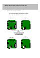
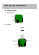
6.3 DESCRIPTIONS OF CONNECTIONS IN SREL, SREL.ZK AND SREL
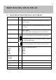
Name
Symbol
Description
Mains adapter
+ / ~
Either positive pole when connected to a direct current
(5 to 24 V DC) or one of the two alternating current connec-
tions (12 V AC)
Mains adapter
- / ~
Either negative pole when connected to a direct current
(5 to 24 V DC) or the second alternating current connection
(12 V AC)
Battery Plug-in connector for a battery (when operated without a
mains adapter)
Battery order code, including plug connector: SREL.BAT
Relay NC Normally closed contact in the relay changeover contact. This
contact is closed against Relay COM when not connected
Relay COM Common contact in the relay changeover contact. This contact
is wired either against an NC relay (break contact) or against a
NO relay (closing contact)
NO relay Normally open contact in the relay changeover contact. This
contact is closed against Relay COM when not connected
External antennas
Brown
White
Green
Grey
Yellow
BN
WH
GN
GY
YL
Connection for colour-coded cables in an external
antenna (Order code: SREL.AV)
Brown
White
Green
Grey
Yellow
RS-485COM
RS-485A
RS-485B
C
A
B
Bus connection for external modules
+ Vaux +V
Type 3.0 - 5.0V +/- 0.5V for external LED or buzzer, max. 10mA
LED / buzzer / Input 1
/ CLS
F3 Multi-function connection
Serial 1 / Input 2 F2 Multi-function connection
Serial 2 F1 Multi-function connection