
Unit installation


LON – Network 3065
Page 14
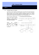
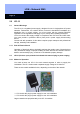
5.2.2 Assembly Instructions
The LPI-10 is intended
for installation in
distribution boxes with
DIN rails. You will also
need an outlet for the
plug-in power supply
of the LPI-10. Depen-
ding on the structural
situation and number
of groups, you can
also put several power
supplies and routers in
one distribution box.
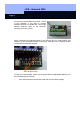
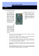
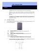
Connect the network cable
(twisted pair) here. You can
also lay a network cable to
the router (if there is one).
Connect the cable to
terminals 17 and 18 there. An
additional network cable goes
from the router to the Lock-
Nodes.
Connect the plug-in
power supply to these
terminals. Make sure
that the polarity (+/-) is
correct. This is printed
on the connecting
terminals. Ground the
LPI-10 on the middle
terminal.
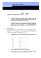
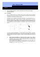
Build the LPI-10 into the separate segments in such a way that there is voltage
of at least 35V DC on each LockNode.
Consequently, the installation location depends on the number and particular
distribution of the LockNodes in the corresponding segment.
If it is not possible to guarantee voltage of 35 VDC at each LockNode with one
LPI-10, you must install a repeater (including power supply) and an additional
LPI-10 (including power supply) in the segment.
The LPI-10, as it comes from the factory, does not have any over voltage
protection. For this reason, this protection should be already provided for by
the customer.
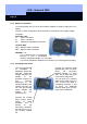
When commissioning the LPI-10 and the network, you must make sure that
the line voltage that is applied is 230V~ (+/- 10%). Higher or lower line voltage
input to the LPI-10 can lead to disturbances in the network.