
Unit installation

WAVENET RADIO NETWORK 3065
Page 22
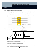
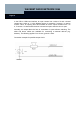
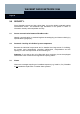
Input 1, pink
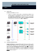
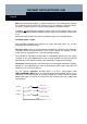
Note: We recommend installing an empty mounting box. This will physically separate
the LockNode from the switch unit. A switch unit, e.g. a dimmer or electronic ballast,
can have a negative impact on communication between LockNode and lock.
In addition, no
switching power supplies must be used (e.g. as a power supply for the
LockNodes). Distance between switching power supply and LockNode / router node:
≥ 2 m.
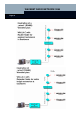
With some switch ranges, less space is available owing to the cover attachment.
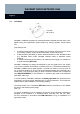
LockNode inputs / output:
Each WaveNet LockNode also features one output and three inputs, e.g. for door
monitoring (except WN.LN.O.I/O).
The three inputs allow up to three external potential-free contacts to be connected.
This allows for the central monitoring of door or bolt contacts, for example, but also
motion sensors, light barriers etc., over the WaveNet network.
The statuses of connected contacts can be interrogated (polled) from the central
computer at any time. Modifications to the contacts (events) can also be reported
automatically to the central computer if the LockNode is configured accordingly.
The output forwards signals to external systems such as signal transmitters, heating,
lighting etc. The output takes the form of an electronic switch (open drain) that can
switch up to 25 V and up to 650 mA.
For the optional activation of I/Os there is a 6-pin colour-coded cable
(WN.LN.SENSOR.CABLE) which is connected to the socket labelled ‘sensor’ on the
LockNode. For monitoring tasks, up to three potential-free contacts can be connected
between the green ‘in common’ line and each of the coloured (pink, grey, yellow) lines
(see diagram).
Contact 1
Contact 2
Contact 3
Input 2, grey
Input 3, yellow
In common, green