
Unit installation

VdS Shunt lock function 3066
Page 13
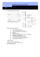
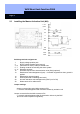
• External light emitting diode
You can connect an external light emitting diode to soldering terminals 3 and 4 for
visual signaling. When the transponder is operated successfully, the LED blinks.
Maximum length of the line: 10 m (33 feet).
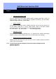
• Switch contacts
Connect them to the alarm system. Soldering terminal 5 is the common contact, 6 is
for the electric strike and 7 for the make contact. Refer to the BAS installer
instructions for the wiring and values for the terminating resistor(s).
Rx: wire jumper; Ry: wire jumper; Rz: terminating resistor
• Sabotage contacts
Connect them to soldering terminals 8 to 11. Solder the Rs resistor (terminating
resistor or short circuit) to soldering pins X27 and X28 (refer to the drawing).
• Global activation suppression (optional)
Applies ground (such as pin 15 or pin 2) to pin 13 over a floating contact so that the
system cannot be activated.
2.3.3 Connecting Deactivation Request, Deactivation Acknowledgement and
Activation Request
Refer to Chapter 2.5.