
Unit installation

VdS Shunt lock function 3066
Page 11
+
8
..16 V
Masse
+LED
- LED
C
NC
N0
SAB0
SAB0
SAB0
SAB0
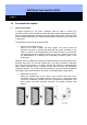
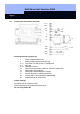
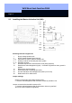
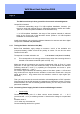
2.3 Installing the Master Activation Unit (MA)
Soldering terminal assignments:
1 Supply voltage positive pole
2 Supply voltage negative pole (ground)
3 + 4 Connection for LED (5 volts) in outside area
5 - 7 Floating contacts for switching the alarm system
8 - 11 Sabotage contacts
12 Activation request from slave activation units (SAs) (optional)
13
Deactivation acknowledgement (input)
→ Activation suppression when ground is
applied
14 Deactivation request (output)
15 Ground (identical to soldering terminal 2)
29 Acoustic activation acknowledgement by BAC (not for DA)
30 Solder terminal for cable screen
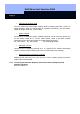
Jumper settings:
Jumper connects right and middle contacts of B1:
⇒ Acoustic acknowledgement after activation release by activation unit
Jumper connects left and middle contacts of B1:
⇒ Acoustic acknowledgement after final activation is done by the BAC
(this is the VdS-compliant configuration).