
Unit installation

VdS Shunt lock function 3066
Page 10
Test the shunt lock function again after you have connected the lock switch contact.
Try to deactivate the locking cylinder or Smart Relay even when the bolts have not
been driven out.
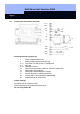
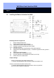
• External light emitting diode
You can connect an external light emitting diode to soldering terminals 3 and 4 so that
you have a visual display in the outside area showing whether the cylinder or Smart
Relay is activated or deactivated. Maximum length of the line: 10 m (33 feet).
• Switch contacts (not used)
Soldering terminals 5 to 7 are not needed for the deactivation unit.
• Sabotage contacts
Connect these to soldering terminals 8 to 11. Solder the Rs resistor (terminating
resistor or short circuit) to soldering pins X27 and X28 (refer to the drawing).
Install other deactivation units, if any, according to the same plan.
2.2.3 Connecting Deactivation Request and Deactivation Acknowledgement
Refer to Chapter 2.5