
Unit installation

VdS Shunt lock function 3066
Page 9
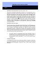
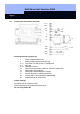
2.2.1 Testing the Deactivation Unit (DA):
To test, connect the deactivation unit to a 9-volt compound battery. Make sure that
the polarity is correct. Position the deactivation unit within radio range of the digital
locking:
Deactivation unit
digital locking cylinder max. 40 cm (16 inches)
Deactivation unit
digital Smart Relay min. 20 cm, max. 1 m (8 till 40 inches)
The ranges depend on the structural circumstances and so will vary.
Make sure that both the deactivation unit and cylinder are correctly programmed
(refer to Chapter 3). Then connect soldering terminals 13 and 15 (ground) to one
another. This deactivates the cylinder/Smart Relay (signal tone for cylinder) and the
LED on the deactivation unit goes out. The cylinder no longer responds to
transponders. When you remove the connection, the cylinder or Smart Relay is
activated. The LED lights again. Repeat the tests several times until the radio link
works perfectly.
☺ You can increase the range between the cylinder and deactivation unit by
using FH version locking cylinders (with plastic inside knob).
Once the deactivation unit successfully passes the test, you can carry out the actual
permanent installation.
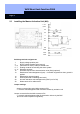
2.2.2 Connecting Power Supply, Lock Contact Evaluation and Sabotage Contacts:
• Power supply
Connect the positive pole of a direct current source between +8 ... + 16 V
(recommended: +12 V) to soldering terminal 1. Note that the voltage is not permitted
to
exceed a value of +16 V under any circumstances.
Connect soldering terminal 2 to ground.
• Optional lock contact evaluation (global activation suppression)
If you want the alarm system to remain inactivated until all doors of the security area
are closed, meaning the bolts have been driven out, you can connect the lock switch
contact to soldering terminals 12 and 15. The lock contact must be a floating electric
strike.
☺ If there is no lock contact (not VdS-compliant), it is, of course, impossible to
check whether all doors have been locked, which means that it is also
possible to activate the alarm system if some doors are not locked. In any
case, however, all cylinders must have been successfully deactivated.
If there is no lock contact, simply do not connect soldering terminals 12 and
15.