
Unit installation

Smart Output Module
Page 12
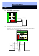
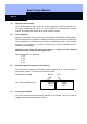
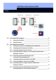
7.4 Protective Circuit for the Signaling Option Outputs
Each pair of terminals opposite one another (1 and 5, 2 and 6, 3 and 7, 4 and 8)
works together. When the lower output in the module is switched, the corresponding
assigned output blinks.
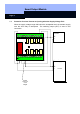
Beleuchteter Taster
Netzteil
+
-
12 VDC
Steuerung
Input a
Input b
|A-|K1|A+| +|K2|8a|8b|7a|7b|6a|6b|5a|5b
I-|I+| B | A | C |4a|4b|3a|3b|2a|2b|1a|1bOut|
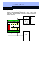
Lit key Control
Power supply
+
-
12 V DC