
Unit installation

Manual – Digital Half Cylinder 3061
Page 13
5. Installation instructions
5.1 General notes
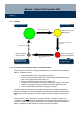
When installing the digital half cylinder, make sure no sources of low-
frequency radio interference are located nearby. There should be at least
0.5 m distance between individual locking cylinders and 1.5 m between Smart
Relays or arming units.
The profile cylinder housing of the half cylinder should not protrude more than
3 mm on the outside. It is also imperative that no water can enter the cylinder
through the actuator area.
Do not strike or hit the knob under any circumstances during installation.
The knob is secured by means of a bayonet lock.
Batteries are already installed in the unit on delivery.
The installation work described in this chapter can only be executed with the
installation/battery tool.
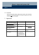
5.2 Programming the half cylinder
The digital half cylinder and the corresponding transponders must be pro-
grammed into the locking plan prior to installation. Please see the software
operating instructions for further details.
& Half cylinders are delivered from the factory in so-called warehouse
mode; communication with transponders is not possible in this mode
(exception: programming transponder). You can deactivate the ware-
house mode using the software or programming device without having
to create a locking plan. Please see the software operating instructions
for further details.
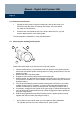
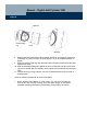
5.3 Installing the half cylinder (except .MR)
Turn the actuator until it is vertical and pointing downwards. Insert the digital half cylin-
der through the lock. Secure the half cylinder in the slot-in lock with the fixing screw.
& Do not strike or hit the knob under any circumstances during installation.
The cylinder must not come into contact with oil, paint or acids.