
Unit installation

Manual – Digital locking cylinder 3061
Page 27
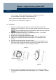
9. Slide the recessed grip ring back onto the knob so that the knob and ring are flush
against each other.
10. Hold the assembly/battery tool against the internal knob so that both nibs fit into
the openings on the ratchet disk (if necessary rotate the knob until the nibs slot into
the openings).
11. Lock the knob by rotating it approx. 30° in a clockwise direction (until you hear a
clicking noise).
Use an authorised transponder to check functionality.
& When replacing the batteries on a ZK version you may have to reset the
time as the clock will stop running when the power supply is interrupted
(software operating instructions: Programming Æ Set locking clock time).
9. Possible uses
9.1 General
The digital locking cylinder is designed to fit locks for Euro profile cylinders
compliant with DIN 18252 and EN1303.
9.2 Fire doors
Installation in fire doors is possible. The locking cylinder version FH should be
used for these doors and for metal doors.
9.3 Doors on escape routes
The .AP model should be installed in anti-panic doors where the position of
the actuator can influence the functionality of the lock. The model must be
approved for use by the lock manufacturer. See also chapter 2.4, standards
DIN EN 179 and DIN EN 1125 and the product data sheets provided by each
lock manufacturer.
9.4 Outdoor installation situations
Unless it is ensured that the door is completely water-proof it is recommendable to use
the .WP version of each respective model. The external knob on anti-panic cylinders is
completely sealed; the entire cylinder is completely sealed on the twin-knob cylinder
version.