
Unit installation


Manual – Digital locking cylinder 3061
Page 22
& Actuators that remain in the highest position will have no effect on the
functionality of approved anti-panic locks pursuant to standards DIN
EN 179 and DIN EN 1125.
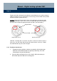
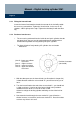
4. If the knob is moved slightly beyond the transition point between the areas
"O" and "S" it must continue to rotate of its own accord until it reaches to
the area marked "U".
Otherwise realign the locking cylinder and fittings or check the lock for
defects.
5. Close the door and repeat the test. If the knob is difficult to rotate you will
need to adjust the door or the striking plate.
6. Then check the same functionality on the external knob after activating
the knob with an authorised transponder (see illustration in chapter 5.4).
The functionality test must be carried out for both directions of rotation.
Note: European standard EN 179 Appendix C recommends that all lock
components should be checked for satisfactory functionality during
emergency exit locks maintenance checks at regular intervals of no
more than one month.
6. Battery warnings
Each locking cylinder has a battery management system that indicates declining
battery power in good time. This helps prevent the batteries from becoming completely
discharged. The battery warning levels are described in the following.
6.1 Locking cylinder
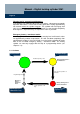
Warning level 1: weak batteries
When a locking cylinder's batteries are running low it will emit eight short
signal tones in rapid succession when operated by a transponder before the
locking cylinder engages. The batteries should be replaced without delay.
Around 15,000 opening or 9 months use of the locking cylinder remain after
battery warning 1 has been triggered.