
Unit installation


Manual – Digital locking cylinder 3061
Page 21
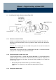
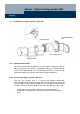
5.4.3 Fitting the internal knob
Screw the internal knob onto the thread; the actuator in the lock will provide
the necessary counterforce. Tighten the inner knob or, in the case of .AP
cylinders, slide it right up to the stop. Tighten the threaded pin with the Allen
key.
5.4.4 Perform a function test
& The test can be performed from the inside for anti-panic cylinders that do
not rotate freely; the test must be performed from the outside with an
authorised transponder for freely rotating anti-panic cylinders.
& The internal knob of freely rotating .AP cylinders has no function
whatsoever.
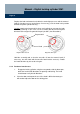
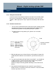
1. With the door open turn the internal knob (see illustration in chapter 5.4)
in both directions within the area marked "U": you will not feel any reset
force.
2. Turn the internal knob to the end of the area marked "L": you should feel
a slight reset force. If you let go of the internal knob in this position it
should move back to the "U" area of its own accord.
Otherwise realign the locking cylinder and fittings or check the lock for
defects.
3. Now rotate the knob through the area marked "S" (you will notice a
distinct increase in reset force) to the area marked "O". Reset force does
not have any effect in this area.
Area U:
Area L:
Area S:
Area O:
lower area without
reset force
slight reset force
strong reset force
upper area without
reset force
Knob
Position of actuator
(concealed)