
Unit installation


Manual – Digital locking cylinder 3061
Page 16
4.4 Emergency connection activated
Locking cylinders installed within a SimonsVoss network can be permanently engaged
automatically via an automated command in the programming software. The signal is
usually transmitted by a fire detection system and can be interpreted by the LDB (if
configured accordingly).
4.5 Time-controlled opening active
This box is checked if the time-switch function has been programmed and the locking
cylinder engaged automatically by the time switch.
4.6 Engaged
This box is checked if the time-switch function or flip-flop mode has been programmed
and the locking cylinder is engaged.
5. Installation instructions
5.1 General notes
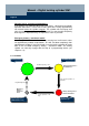
When installing the digital locking cylinder, make sure no sources of low-
frequency radio interference are located nearby. There should be at least
0.5 m distance between individual locking cylinders and 1.5 m between Smart
Relays or arming units.
The profile cylinder housing of the locking cylinder must not protrude more
than 3 mm on the outside; use a profile cylinder collar where necessary. It is
also imperative that no water can enter the cylinder through the actuator area.
Do not strike or hit the knobs under any circumstances during installation.
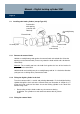
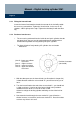
Both knobs are closed by means of bayonet locks (exception: internal anti-
panic version).
The inside part of the locking cylinder is identifiable by a sticker (IL for inside
length) on the profile cylinder housing, and also by the black plastic ring
located between the internal knob and the profile cylinder housing.
Batteries are already installed in the unit on delivery.
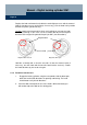
The installation work described in this chapter can only be executed with the
installation/battery tool.