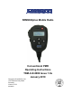
SRM9020plus Mobile Radio Conventional PMR Operating Instructions TNM-U-E-0086 Issue 1.0a January 2010 Comgroup Australia Pty. Ltd.
SRM9020plus ~ PMR Operating Instructions ASSOCIATED DOCUMENTATION The following documentation is available for use with the SRM9000 series of products: TNM-I-E-0005 SRM9000 Series Installation Instructions TNM-M-E-0001 SRM9000 Service Manual TNM-U-E-0003 SRM9030 PMR Operating Instructions TNM-U-E-0004 SRM9030 Trunked Operating Instructions TNM-U-E-0012 SRM9020 Trunked Operating Instructions TNM-U-E-0014 SRM9025 PMR Operating Instructions TNM-U-E-0015 SRM9025 Trunked Operating Instructions To ord
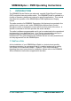
SRM9020plus ~ PMR Operating Instructions DOCUMENT BASED ICONS The following icons are used in this document to describe certain actions of the screen display: This icon indicates that the first screen is only displayed momentarily and then the second screen is displayed. This icon indicates that the screens shown are each displayed momentarily in sequence. SAFETY 1. Do NOT operate your radio, without a handsfree kit, whilst driving a vehicle. 2. Do NOT operate your radio in an explosive atmosphere.
SRM9020plus ~ PMR Operating Instructions CONTENTS ASSOCIATED DOCUMENTATION ............................................................ I ABOUT THIS DOCUMENT......................................................................... I DOCUMENT BASED ICONS..................................................................... II SAFETY ..................................................................................................... II HINTS FOR USING THE RADIO ................................................
SRM9020plus ~ PMR Operating Instructions 6.1.2 Mute Adjust ...................................................................... 18 6.1.3 Alert Volume..................................................................... 18 6.1.4 Information ....................................................................... 19 6.1.5 Network ............................................................................ 19 7. SPECIAL FUNCTION BUTTONS .................................................. 20 7.1 Monitor........
SRM9020plus ~ PMR Operating Instructions 1. INTRODUCTION The SRM9000 Series Radios are advanced, versatile Digital Signal Processor (DSP) controlled, two-way mobile radios. The SRM9000 Series is available in a number of frequency bands and versions for specific applications. This manual describes the operation of the SRM9020plus PMR Alphanumeric Display variant.
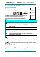
SRM9020plus ~ PMR Operating Instructions 2. FRONT PANEL CONTROLS Volume Up Volume Down F2 - Function Microphone On/Off PTT Icons Display Scroll Up F3 - Return to Menu F4 - Scan On/Off or Send Selcall F1 - Change Menu Scroll Down BUTTON/ CONTROL On/Off FUNCTION PTT/Pressel M (Menu) F1 F3 S (Select) F4 Push and hold for 1 second to switch the radio On or Off. Press-to-Talk switch. Move between Menu Screens. Used to return to the Main Menu Screen.
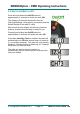
SRM9020plus ~ PMR Operating Instructions 3. FUNCTIONS AND FACILITIES Icons 3.1 DISPLAY AND ICONS The display shows text information relevant to the selected Menu Screen. Valid Signal Invalid Signal Searching The Name field (e.g. Ch73) shows the selected entry from the current screen (e.g. from the Channel List). Several Icons can be individually displayed as shown below: Scanning Stored Call ICONS Valid signal + CTCSS (and Selcall) is being received. Audio can be heard from the loudspeaker.
SRM9020plus ~ PMR Operating Instructions 3.2 SWITCH-ON/SWITCH-OFF Press and hold down the On/Off button for approximately 2 seconds to switch the radio ON. The display will illuminate and briefly show an 'Opening Message’ (arranged by your dealer) and the Selcall Identity of the radio (if used). After a brief time the display will show the selected channel, at which time the radio is ready for use. Pressing and holding the On/Off button for approximately 2 seconds will switch the radio Off.
SRM9020plus ~ PMR Operating Instructions 3.3 VOLUME ADJUSTMENT The Volume Up/Down buttons set the speech level at the loudspeaker. Use the Up/Down buttons to set the volume of the received signal to the required level. When there is no signal a beep will be emitted at each button press to indicate the volume level. During a call the beeps are omitted. Note: The radio may be programmed so that the volume cannot be turned off completely. 3.4 RECEIVING The radio will listen on the displayed Channel.
SRM9020plus ~ PMR Operating Instructions 3.5 TRANSMITTING To avoid interfering with other users of the channel, listen first to ensure no transmissions are occurring. Make sure the busy Icon is not shown. Remove the microphone from its cradle. Hold the microphone a few centimetres from the mouth, press the “Press-toTalk” (PTT) button. Speak clearly across the face of the microphone in a normal conversational manner.
SRM9020plus ~ PMR Operating Instructions 3.6 SELCALL FUNCTIONS 3.6.1 Receiving a Selcall A number of different options can be set up by your dealer to sound various alert tones when a selcall is received. Consult your dealer for a detailed explanation of your radios set up. Generally, removing the microphone form its cradle or pressing the PTT will stop any alerts and answer a received call. 3.6.2 Sending a Selcall Refer to Phonebook Screen (Section 5.2) and Status Screen (Section 5.
SRM9020plus ~ PMR Operating Instructions 3.7 SCAN FUNCTIONS Scanning consists of sequentially searching up to 15 channels for a valid signal (RF+CTCSS tone). When found, the radio will stop on that channel until the signal disappears again. If a Priority Channel is assigned, the radio will interleave a check of this channel between each normal channel check. The radio may also check the Priority Channel every few seconds while stopped on a channel.
SRM9020plus ~ PMR Operating Instructions The buttons allow access to the other screens (not Main Channel Screen). When these other menus time-out, the display returns to the Scan Screen. The Radio may be programmed so that the Microphone needs to be on-cradle for the radio to scan. If the Microphone is left off-cradle for too long then the radio will sound a continuous alert tone until it is replaced. In the Scan Screen the function buttons are assigned as follows. M Go to other menus.
SRM9020plus ~ PMR Operating Instructions 3.8 MUTE LEVEL SETTING The Mute Adjust Screen is accessed from the Setup menu, or (when assigned) by means of a programmed function button. When the Mute Adjust Screen is selected the buttons allow the Radio Mute level to be adjusted. The level is stored when the Screen is exited via the S button, or times-out. 3.9 EXTERNAL ALERT Provision is made to connect an external alerting device to the rear of the radio.
SRM9020plus ~ PMR Operating Instructions 4. MENU SYSTEM The SRM9020plus radio software uses a programmed Menu structure to enable the operator to access all of the radio options. The structure of the menu (comprising up to eleven screens) can be programmed to meet the specific needs of individual customers. The diagram on the following page illustrates the default menu structure for which the radio is programmed at manufacture.
SRM9020plus ~ PMR Operating Instructions 4.1 MENU NAVIGATION Navigation Buttons M Move through the available Main Screens S Select Setup Sub-Menu Scroll Up/down though Menu Lists F3 Return to Main Menu Default Channel This diagram shows a sample of available menu options. The number of options and order in which they are accessed will vary between individual installations. © Comgroup Australia 2010 Page 24 TNM-U-E-0086 Issue 1.
SRM9020plus ~ PMR Operating Instructions 5. MAIN MENU SCREENS 5.1 CHANNEL SCREEN The Channels Screen shows the currently selected channel and allows it to be changed. The Name field (e.g. Ch73) shows the selected entry from the current screen (e.g. from the Channel List). 5.2 PHONEBOOK SCREEN This Screen need only be accessed if Selcall is used. Selcall Identity information is stored for various users and calls can be placed to them from this Screen.
SRM9020plus ~ PMR Operating Instructions 5.3 STATUS SCREEN This Screen need only be accessed if Selcall is used. Selcall Status is stored here and can be sent from this Screen. From the Main Channel Menu press the M button until Status is briefly displayed. The display will quickly be replaced by the Saved-Status-Value. The entries. buttons scroll through the Status List Pressing the S button will send the displayed Status to the Current-Phonebook-Entry. Press the M button to go to other Menu Screens.
SRM9020plus ~ PMR Operating Instructions 5.4 STORED CALLS SCREEN This screen allows the eight most recent missed Selcalls (calls not answered before the Alert-tone stops) and received Status Selcalls to be reviewed. From the Main Channel Menu, press the M button until Stored is displayed. If there are entries in this menu, the display will quickly change to show the most recently received calls. The icon will show in the Main Channel Menu when there is an entry in this Menu.
SRM9020plus ~ PMR Operating Instructions 5.5 SETUP SCREEN Use this Screen to access the other Setup submenus. From the Main Channel Menu, press the M button until Setup is displayed. Press the S button to access the submenus. When a submenu is displayed, press the M button to select other submenus. Refer to Section 6 for a detailed description of available submenus. © Comgroup Australia 2010 Page 24 TNM-U-E-0086 Issue 1.
SRM9020plus ~ PMR Operating Instructions 6. SETUP The Setup sub-menus allow the operator to modify the operation of some of the general functions of the radio. The programmer can restructure or restrict access to any or all of these menus according to specific requirements. 6.1 SETUP SUB-MENUS The default Setup sub-menu structure is shown in the Menu Navigation diagram.
SRM9020plus ~ PMR Operating Instructions 6.1.2 Mute Adjust Use the Menu Screen to view and change current Mute setting. Use the buttons to change the Mute level. Use the S button to return to the Channel Screen. Note : When a Voting channel is selected the Voting-Mute level is shown, but may not be changed. Press the 6.1.3 M button to change to the Alert Volume submenu. Alert Volume This Screen allows you to set the level of the Alert Volume Beep Tone in relation to the current Volume setting.
SRM9020plus ~ PMR Operating Instructions 6.1.4 Information This Screen displays information that identifies the Radio Serial Number Software Version and Own Identity. The screen switches alternately between Software Version and Own Identity. This is a read only Screen, press the S button to go to the Channel Screen. Press the 6.1.5 M button to change to the Network submenu. Network The Network Screen allows you to switch operation between; • PMR and. • Trunk Network 1, or 2 (when available).
SRM9020plus ~ PMR Operating Instructions 7. SPECIAL FUNCTION BUTTONS This Section lists Functions that may be programmed to the (F4) buttons in the Main Channel screen. F2, F3 and S Consult your Simoco Dealer as to which functions have been programmed in your radio. 7.1 MONITOR Opens/Closes the audio (signalling) mute. Only valid on Non-Community Repeater type channels and/or Closed Selcall channels without Receiver Lockout programmed. The display briefly shows ON or OFF when the button is pressed. 7.
SRM9020plus ~ PMR Operating Instructions 7.8 MUTE Provides direct access to the Mute Setup screen and allows the user to change the mute level from that screen. 7.9 EXTERNAL ALERT Enables/Disables control of External Output via Selcall Decodes. The display briefly shows ON or OFF when the button is pressed. 7.10 GOTO CHAN A, B, C, D Selects predefined Channel A, B, C or D, and returns on the second press. The Defined Channel is redefined to the current channel if held for approximately 2 seconds.
SRM9020plus ~ PMR Operating Instructions 8. OPTIONS The following options are available, contact your dealer for further information. 8.1 QUICK RELEASE TRANSCEIVER KIT This kit provides a mounting cradle to allow the Transceiver to be quickly removed without having to undo unnecessary screws. 8.2 MICROPHONE/CONTROL HEAD EXTENSION LEAD This lead allows the Transceiver to be placed up to 4.5 metres from the Control Head. 8.
SRM9020plus ~ PMR Operating Instructions 9. TROUBLESHOOTING If, after reading this guide, you are unable to switch the radio on, check the following: • A fuse has not blown. Your installer should advise you of the location of the two fuses, • The power supply cables and their connections are secure, and • The vehicle battery is charged. If these checks are OK, contact your dealer or Simoco representative for further advice. © Comgroup Australia 2010 Page 23 TNM-U-E-0086 Issue 1.
SRM9020plus ~ PMR Operating Instructions APPENDIX A - ALERT TONES AND MESSAGES Key Press 0.05 Off 440Hz 880Hz 1480Hz All durations indicated in seconds 0.05/0.05 Error Tone 0.1 Beep Alert Bip Alert 0.1 0.1/0.1 2 x Bip Alert Ring Alert Telephone Ring Tone 0.19/0.19 Urgent Alert Continuous Alert © Comgroup Australia 2010 Continuous Page 24 TNM-U-E-0086 Issue 1.
SRM9020plus ~ PMR Operating Instructions APPENDIX B - GLOSSARY A summary of common radio terms as used in this document, and their meanings, are given below. Alert tones The transceiver emits these tones to indicate an invalid operator or error. Cradle The bracket that holds the microphone when not in use. Current Phonebook Name that would be shown were the Phonebook screen shown. Entry DSP DTMF Icon Digital Signal Processor. Dual Tone Multi-Frequency (a Signaling method).
Hereby, Comgroup Australia Pty Ltd declares that this product is in compliance with the essential requirements and other relevant provisions of Directive 1999/05/EC. © Comgroup Australia 2010 TNM-U-E-0086 Issue 1.