
Installation Manual


PULSE AIR DATA MODEM TNM-M-E-0055
Jan 17 Page 18 Issue 1.0
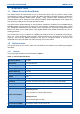
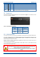
2.2.2 Power Connection
The DC power input is via a 3-way screw terminal connector (Weidmuller Onimate Signal – series
BLA/SLA 5.08). The three pins are wired to suit the voltage range shown in Table 7 below. Pin 1
of the 3-way screw connector is shown in Figure 4 below.
Figure 4: Pin 1 of the 3-way screw connector
Table 7. DC Power Connector Pin-outs.
Pin
Description
1
0V
2
+12.0 to +14.0 V
3
Not Connected
The equipment must be installed so that the power socket is readily accessible.
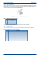
2.2.3 COM Serial Port
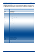
The connector pin-outs for the 9-way D Type ‘COM’ Serial Port are shown below in Table 8.
Table 8. COM Serial Port Connector Pin-outs.
Pin
Function
1
Data Carrier Detect (DCD). Connected to pin 4 and 6
2
Tx 1
3
Rx 1
4
Data Terminal Ready (DTR). Connected to pin 1 and 6
5
0 V
6
Data Set Ready (DSR). Connected to pin 1 and 4
7
NC
8
NC
9
NC