
Installation Manual

PULSE AIR DATA MODEM TNM-M-E-0055
Jan 17 Page 17 Issue 1.0
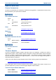
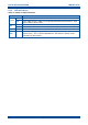
Pwr
Green
Permanently on (not software controlled).
F1
For future use.
F2
For future use.
F3
For future use.
F4
For future use.
RSSI
-dBm
The LEDs are progressively activated as the signal level increases
to the various levels, 120 – 50 in 10 dB steps.
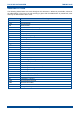
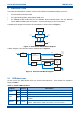
2.2 CONNECTIONS
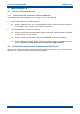
The connectors on the Pulse Air Data Modem are shown below in Figure 3. The functions of each
connector are detailed in Table 6.
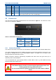
Figure 3. Data Modem Connectors.
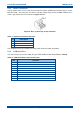
Table 6. Data Modem Connections.
Connector #
Conn Type
Function
PWR
Power I/P
ANTENNA
SMA
(female)
Antenna
COM
D Type
(female)
Serial Port
2.2.1 Antenna Connection
The antenna connection on the Pulse Air Data Modem is provided with a 50 Ω female SMA socket.
The Voltage Standing Wave Ratio (VSWR) of the antenna connection should be tested prior to use
by using of a suitable test set, e.g. an Anritsu/Wiltron S331A. A VSWR of 1.5:1 or better at the
relevant frequencies should be ensured.
Mating connectors should be galvanically compatible with nickel outer and gold centre pin to
minimise passive intermodulation.
It is recommended that a good quality flexible co-axial cable is used, e.g. with double-screening
braid and multi-strand copper inner.
CAUTION
The Antenna System should be protected against lightning by means of an
earthing system and surge protection device.
Do not connect Antenna Lightning conductors to the base station or Mains
Earth.