
Installation Manual

PULSE AIR DATA MODEM TNM-M-E-0055
Jan 17 Page 16 Issue 1.0
2 DESCRIPTION
The Pulse Air Data Modem consists of three main Printed Circuit Boards (PCBs), these are:
the RTU Modem Interface PCB;
the Light Emitting Diode (LED) Display PCB; and
the SDD690 Radio PCB based on the SDP600 Series Portable Radio. See the SDP600
Series DMR Portable Radio Transceiver – Service Manual[1] for more information.
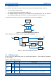
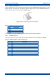
A simple block diagram of the Pulse Air Data Modem is shown below in Figure 1.
Figure 1. Data Modem Simple Block Diagram.
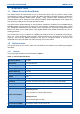
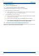
A block diagram of the Interface PCB is shown below in Figure 2.
Figure 2. Interface PCB Block Diagram.
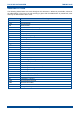
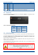
2.1 LED INDICATIONS
On the front of the Data Modem there are several LED indicators. There details are explained
below in Table 5.
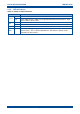
Table 5. Details LED Indicators.
Legend
Colour
Description
Radio
Tx
Activated for ~500 ms when radio is transmitting.
Rx
Activated for ~500 ms when radio is receiving.
Com
Tx
Activated for min ~200 ms when serial data is input to the modem.
Rx
Activated for min ~200 ms when serial data is output from the
modem.
System
OK
Green
Active (ON) when the radio is in its operational mode and has
service. OFF when in FPP, error states, or not in service.
Voltage
Regulator
U1
5V0
Regulator
2V8
Regulator
RS232
Driver
2V8 to 5V0
Level
Shifter
LED PCB
SDD690
Radio Modem Engine
12V - 14V
DC In
8V0
8V0
2V8
5V0
5V0
5V0
Serial
2V8 I C
2
5V0 I C
2
IC
2
V
IN
IC
2
O/P to
9-way
D Type
O/Ps to
LEDs
5V0
LED
Display Board
SDD690
Radio Modem Engine
RTU Modem
Interface PCB
IC
2V8
2
TTL
Serial
8V0
Supply
IC
5 V
2
5 V Supply
Antenna
RS232
Serial
12 - 14 V
Supply