
User's Manual
SDB680 – INSTALLATION GUIDE TNM-I-E-0046
Aug 14 Page 28 CONFIGURATION TIER II BASE
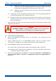
13.2. On the Site View tab of the Navigation Pane, from the navigation tree, click on the
‘System’ branch to expand it. Click on the ‘Site 1’ node displayed.
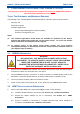
13.3. On the Ribbon bar, select the ‘Add Digital Base’ button to add a digital base to Site 1
on the navigation tree.
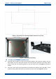
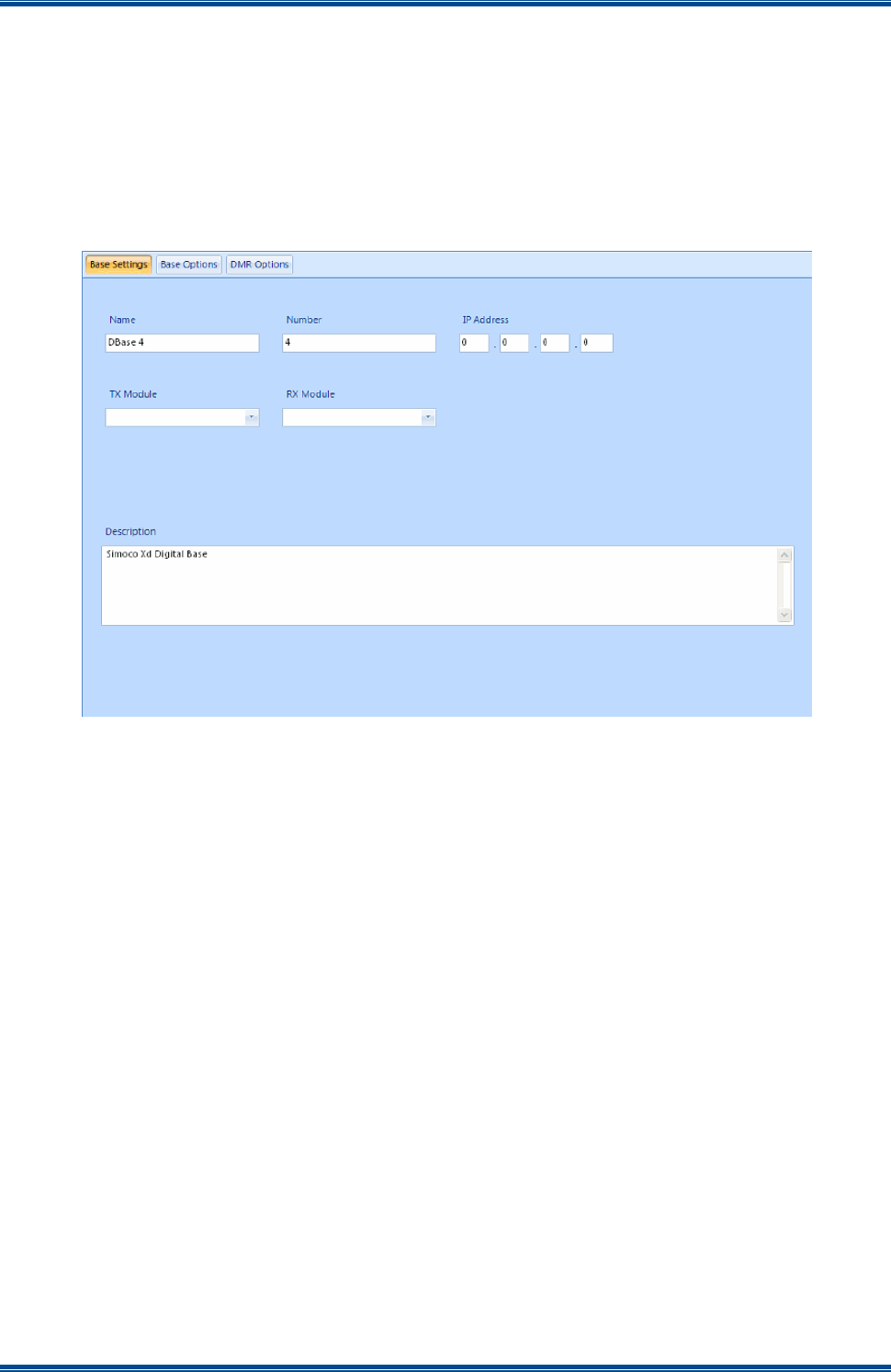
13.4. On the Site View tab of the Navigation Pane, from the navigation tree, select the new
DMR Base that has just been added to the navigation tree. The Base configuration
page will be displayed in the configuration page area (see Figure 10 below).
Figure 10. Base configuration page – Base Settings tab.
13.5. On the base Configuration page on the Base Settings tab, set the ‘IP Address’ to that
sent to the base with the IP Configuration tool.
13.6. On the tab of the base configuration page, select the icon that is displayed to save
the changes that have been made to the configuration page.
13.7. Create a working configuration that includes the new DMR Base in accordance with the
SDMT User Manual [2] and appropriate for the system in which it is installed.
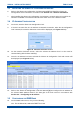
13.8. On the DMR Tier II ribbon bar, select the ‘Write’ button. The ‘Write Base(s)’ page will
be displayed (see Figure 11 overleaf) and any open base configuration pages will be
closed.
13.9. On the ‘Write Base(s)’ page, carry out the following:
13.9.1. Select the new DMR Base that is included in the working configuration.
13.9.2. Select the ‘Write’ button. A progress bar will briefly be displayed.
13.9.3. After a few seconds, check that a green dot appears in the Success column
for the selected base (indicating that the Write operation has been successful)
and a ‘Reboot’ button appears at the bottom of the page.