
User's Manual
SDB680 – INSTALLATION GUIDE TNM-I-E-0046
Aug 14 Page 25 RACK MOUNT INSTALLATION
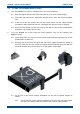
5.3.2. Adjust the rack mount support assemblies to the correct length and secure
them to the rear rack mounting support rails using the four M6 x 16 mm pan
head pozidriv retaining bolts and cage nuts (two each per side).
5.3.3. Tighten the four M6 nuts that secure the front and rear rack mount support
brackets together.
5.4. Fit M6 cage nuts into the appropriate positions on the front rack mounting support rails
so that the base station can be secured into the rack.
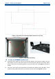
5.5. Pull out the slide runners and fit the base station onto the runners. Ensure that the
keyhole standoffs on the base station (two per side) are correctly located in the keyhole
slots on the slide rails.
6. Secure the base station into the rack using the four M6 x 12 mm pozidriv retaining screws
(with plastic cup washers).
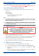
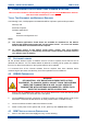
CAUTION
EQUIPMENT DAMAGE. During installation operations, the Torque settings
must be adhered to or damage to the equipment may result.
7. Tighten all four of the M6 screws to a torque of 2 Nm to secure the base into the rack.
2.3 ELECTRICAL CONNECTIONS
8. Refer to the Electrical Connections section, for full details of all connections and the
connector pin-outs.
9. Using a suitable test set, e.g. an Anritsu/Wiltron S331A, check the Tx and Rx antenna
connections for a VSWR of 1.5:1 or better at the relevant Tx and Rx Frequencies.
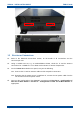
10. On the SDB680 rear panel, carry out the following:
10.1. Connect the Tx and Rx antenna cables to their respective N-type connectors.
10.2. Ensuring that the power source is switched off, connect the DC power cable from the
‘DC IN’ connector to the power source.
11. Carry out the configuration of the SDB680 in accordance with Section 3 – Configuration of
New Tier II Base Station or Section 4 – Configuration of New Tier III Base Station as
appropriate.