
User's Manual
SDB680 – INSTALLATION GUIDE TNM-I-E-0046
Aug 14 Page 23 RACK MOUNT INSTALLATION
2 RACK MOUNT INSTALLATION PROCEDURE
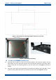
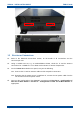
The SDB680 Base Station is designed to be fitted in a standard 403 mm (19”) rack. This
procedure should be followed when installing all new SDB680s into a 19” racking system.
TOOLS, TEST EQUIPMENT AND MATERIALS REQUIRED
The following Tools, Test Equipment and Materials will be required to perform this procedure:
Pozidriv Screwdriver
4 x M6 x 12 mm Pozidriv Retaining Bolts
4 x M6 x 16 mm Pozidriv Retaining Bolts
8 x M6 Nuts and Plain Washers
M6 Cage Nuts
Anritsu/Wiltron S331A Test Set
Earth Bonding Test Set
2.1 RACK PREPARATION
Note.
Rack runner fittings differ between the various rack manufacturers. If the procedure
described below does not apply to the type of rack being used, the procedure should
be modified to suit.
1. Ensure that the rack chosen for installation is firmly bolted together and is securely anchored
to the floor or wall to prevent overbalancing.
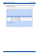
2. In the rack, plan out the locations of equipment before commencing installation.
Notes:
(i).
Each SDB680 requires 2U height of rack space.
(ii).
Unused space should be blanked off to prevent uncontrolled circulation of air.
(iii).
If used, the associated PSU TRAY requires either 1U or 2U height of rack space and is
designed to locate adjacent to the base station.
(iv).
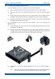
When the SDB680 is installed into a rack, support shelves or side slide runners should
be used. These are available from Simoco and supplied as a pair with all the
necessary screws for securing them.
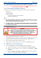
CAUTION
EQUIPMENT DAMAGE. When the SDB680 Base Station is installed into a rack,
DO NOT use the front panel attachment points to support the full weight of the
equipment or damage to the equipment may result. Suitable shelves or
supports MUST be provided to support the body of the base station along the
length of each side.
3. Unpack all the equipment and retain the packaging.