
User's Manual
SDB680 – INSTALLATION GUIDE TNM-I-E-0046
Aug 14 Page 22 WALL MOUNT INSTALLATION
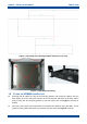
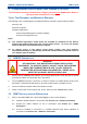
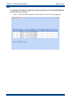
Figure 5. Keyhole Standoff mounting locations.
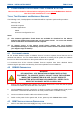
Figure 6. Base Station secured to Wall Mount.
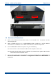
1.3 ELECTRICAL CONNECTIONS
12. Refer to the Electrical Connections section, for full details of all connections and the
connector pin-outs.
13. Using a suitable test set, e.g. an Anritsu/Wiltron S331A, check the Tx and Rx antenna
connections for a VSWR of 1.5:1 or better at the relevant Tx and Rx Frequencies.
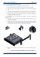
14. On the SDB680 Base Station rear panel, carry out the following:
14.1. Connect the Tx and Rx antenna cables to their respective connectors.
14.2. Ensuring that the power source is switched off, connect the DC power cable from the
‘DC IN’ connector to the power source.
15. Carry out the configuration of the SDB680 in accordance with Section 3 – Configuration of
New Tier II Base Station or Section 4 – Configuration of New Tier III Base Station as
appropriate.