
User's Manual
SDB680 – INSTALLATION GUIDE TNM-I-E-0046
Aug 14 Page 20 WALL MOUNT INSTALLATION
1 WALL MOUNT INSTALLATION
This Procedure should be followed when installing all new DMR Base Stations with a Wall
Mount cabinet.
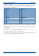
TOOLS, TEST EQUIPMENT AND MATERIALS REQUIRED
The following Tools, Test Equipment and Materials will be required to perform this procedure:
Electric Drill (preferably with Hammer Action)
7.5 mm Drill Bit
Spirit Level
Screwdriver
4 x M4 x 12 Screws (supplied)
4 x Rawlplugs (supplied)
4 x No. 12 x 1½” Woodscrews (supplied)
4 x M6 x 12 mm Pan Head Pozidriv Retaining Bolts
4 x Plastic CupWashers
Anritsu/Wiltron S331A Test Set
Earth Bonding Test Set
1.1 INSTALLATION OF THE WALL MOUNT UNIT
1. Unpack all the equipment and retain the packaging.
2. Establish the mounting position of the base station.
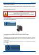
CAUTION
Before drilling any walls, first check for any buried cables or pipes.
3. Ensure that there are no buried pipes or cables in the vicinity.
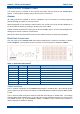
4. Referring to Figure 3 (overleaf), mark out the four holes required to secure the wall mount to
the wall.
5. Using the drill and 7.5 mm drill bit, drill the four holes to a depth of 50 mm.
6. Place the four masonry rawlplugs into the four holes and ensure they are fully inserted. If
necessary, use a small hammer to drive them fully home.
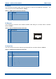
7. Attach the two wall mount brackets to the wall mount case using M6 nuts and washers (see
Figure 4 overleaf).
8. Using the M5 nuts and washers, fit the wall mount inner chassis plate into the wall mount unit
(see Figure 4 overleaf).
9. Using a screwdriver and the four No. 12 x 1.5” woodscrews, secure the wall mount unit to the
wall surface.