
User's Manual
SDB680 – INSTALLATION GUIDE TNM-I-E-0046
Aug 14 Page 19 ELECTRICAL CONNECTIONS
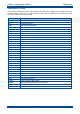
S1 Facilities Connector
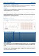
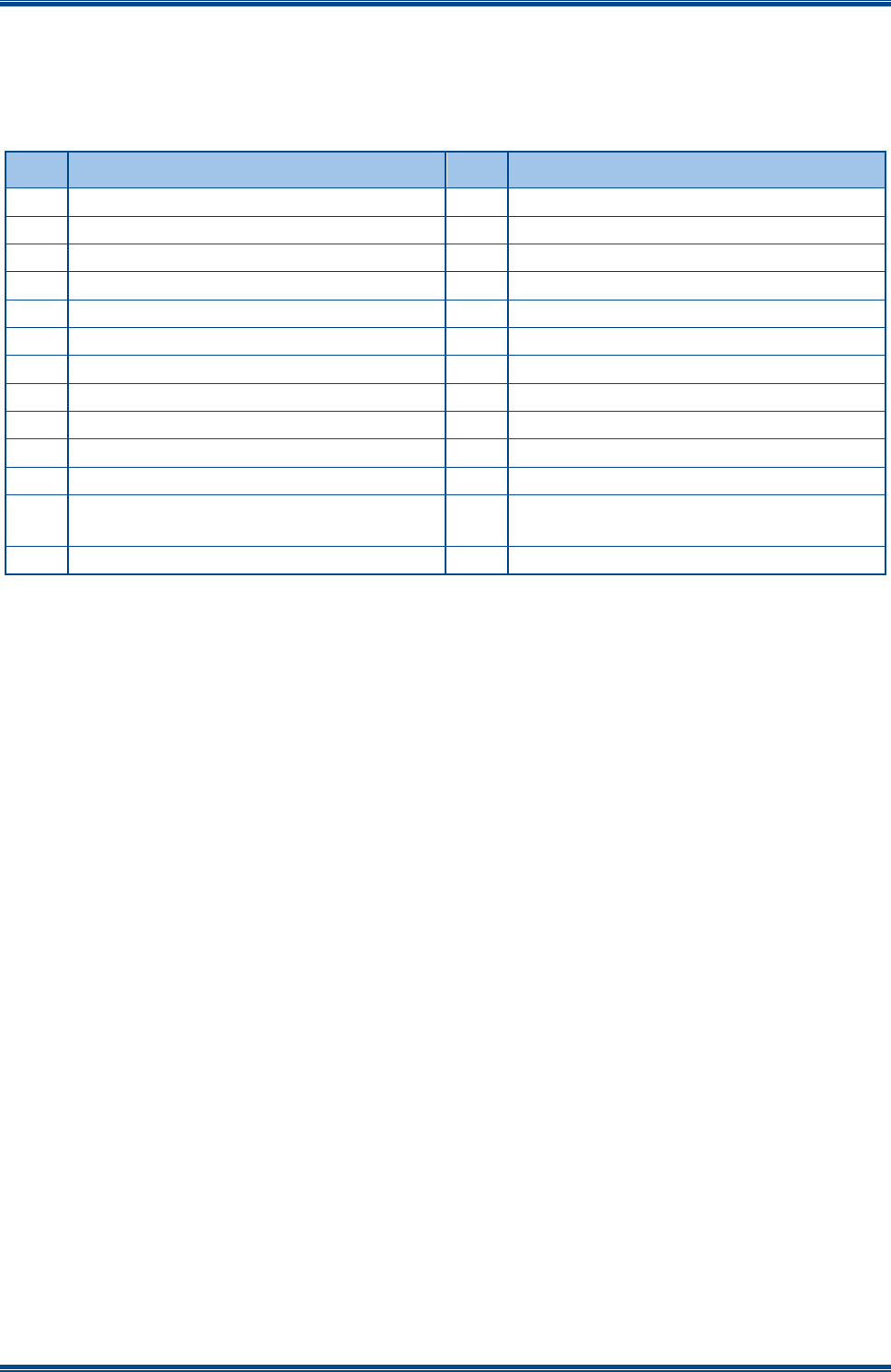
The 25-way D Type facilities connector can be programmed for any combination of digital inputs
and outputs. The connector pin-outs for the Facilities Connector are shown below in Table 7.
Table 7. Facilities Connector Pin-outs.
Pin
Function
Pin
Function
1
Digital Input
14
Digital Output
2
Digital Input
15
Digital Output
3
Digital Input
16
Digital Output
4
Digital Input
17
Digital Output
5
Digital Input
18
Digital Output
6
Digital Input
19
Digital Output
7
Digital Input
20
Digital Output
8
Digital Input
21
Digital Output
9
GPS Rx +
22
GPS Rx -
10
GPS Tx +
23
GPS Tx -
11
1PPS Rx +
24
1PPS Rx -
12
Digital to Analogue Converter (DAC)
Output
25
0 V
13
Supply Voltage
Maximum current provided by the supply voltage pin (pin 13) is 1 A protected by a self resetting
fuse.
The Digital Outputs are open collector and able to sink 300 mA each; the total for all outputs must
not exceed 600 mA.
Digital inputs are active low. Digital high voltages should not exceed 20 V.
The GPS Rx and 1PPS Rx connections are Differential RS422.
The “Analogue Out” connection is between 0 V and 5 V and software controlled to indicate various
functions e.g. Received Signal Strength Indication (RSSI) level.