
User's Manual
SDB680 – INSTALLATION GUIDE TNM-I-E-0046
Aug 14 Page 17 ELECTRICAL CONNECTIONS
Mating connectors should be galvanically compatible with nickel outer and gold centre pin to
minimise passive intermodulation.
A minimum of 85 dB transmit-receive isolation should be provided by the antenna system and
associated filters.
It is recommended that a good quality flexible co-axial cable is used, e.g. with double-screening
braid and multi-strand copper inner.
CAUTION
The Antenna System should be protected against lightning by means of an
earthing system and surge protection device.
Do not connect Antenna Lightning conductors to the base station or Mains
Earth.
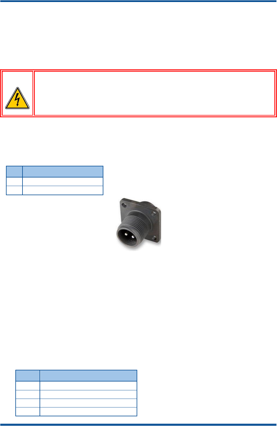
Power Connection
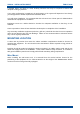
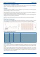
The DC power input is via a 2-pin IP67 DC plug connector. The two pins are wired to suit the
voltage range shown in Table 2 below.
Table 2. DC Power Connector Pin-outs.
Pin
Description
1
+14.0 V
2
Ground
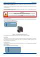
Figure 2. 2-pin IP67 DC Power Connector.
The equipment must be installed so that the power socket is readily accessible.
Earth Point
The earth stud on the rear panel is provided for protective earthing of the equipment. This should
be connected using heavy duty earthing wire with as few bends as possible, typically 6 mm
Green/Yellow with 5 mm eyelet tag.
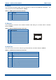
P3 USB A Dual
The USB Type A connector is used as the host connection. The connector pin-outs are detailed
below in Table 3.
Table 3. USB Type A Connector Pin-outs.
Pin
Function
1
Vcc (+5 V)
2
Data -
3
Data +
4
Ground