
User's Manual
SDB680 – INSTALLATION GUIDE TNM-I-E-0046
Aug 14 Page 16 ELECTRICAL CONNECTIONS
ELECTRICAL CONNECTIONS
This section gives an overview of the external connections that are made to the SDB680 Base
Station. It also provides details of the pin-outs for these connections.
GENERAL
All cabling should be installed so that the equipment can be accessed for servicing purposes
without straining the cables or connectors used.
Where equipment is rack mounted, cables must be run so that the unit can be fully withdrawn on
its runners without straining, catching or pinching any of the cables.
Cables should be dressed into cable trays etc where available and run so as to reduce likelihood of
damage from vermin or adverse environments.
Multi-strand wires must be used wherever the wire will be flexed by accessing the equipment.
REAR PANEL CONNECTORS
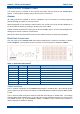
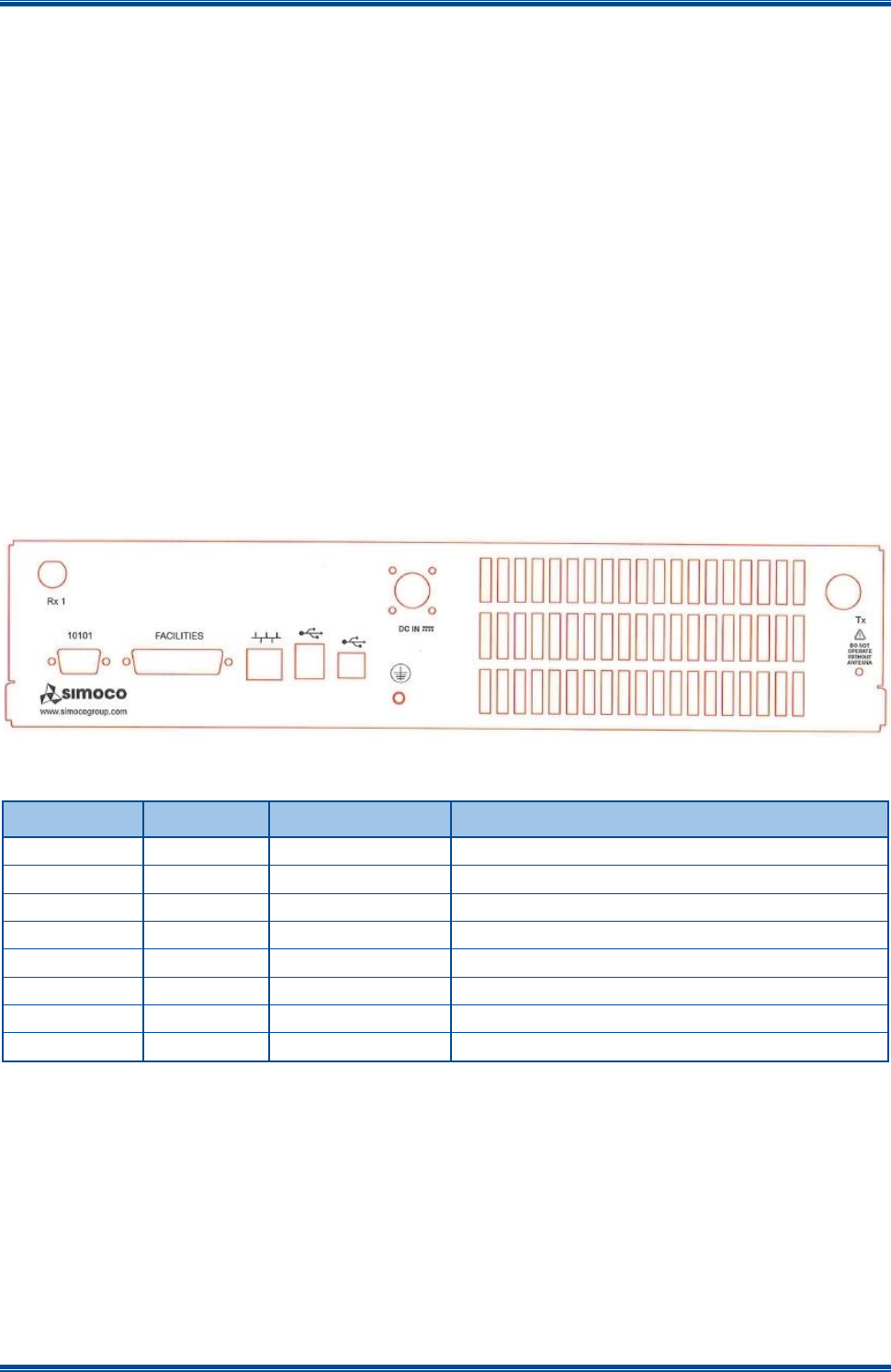
The rear panel of the SDM680 DMR base station showing all the external connections is shown
below in Figure 1. The functions of each connector on the rear panel are detailed in Table 1.
Figure 1. Layout of Rear Panel.
Table 1. Rear Panel Connections.
Connector #
Conn Type
Function
Description
DC IN
Power I/P
14.0 V DC power input
S2
RS232
Serial Port
S1
D Type
Facilities
P5
RJ45
Ethernet
10/100 base-T RJ45 Ethernet connector
P4
USB Type B
Peripheral
USB peripheral interface
P3
USB Type A
Host
USB interface
Tx
N Type
Tx O/P
RF Power output from the Tx
Rx 1
BNC
Rx I/P
Rx input for full duplex operation
Tx/Rx Connections
The Tx antenna connection on the SDB680 Base Station is provided with a 50 Ω female N-type
socket, while for the Rx antenna connection a 50 Ω female Bayonet Neill-Concelman (BNC) socket
is used.
The Tx antenna cable connections must be made with 50 Ω N-type on flexible tails. The Voltage
Standing Wave Ratio (VSWR) of the Tx and Rx connections should be tested prior to use by using
of a suitable test set, e.g. an Anritsu/Wiltron S331A. A VSWR of 1.5:1 or better at the relevant Tx
and Rx frequencies should be ensured.