
User Manual

SDB670 – SERVICE MANUAL TNM-M-E-0032
May 13 Page 28 DESCRIPTION
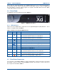
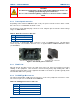
4.3.8 Facilities Connector
The 25-way D Type facilities connector can be programmed for any combination of digital inputs
and outputs.
The connector pin-outs for the 25-way D Type Facilities Connector are shown below in Table 14.
Table 14. Facilities Connector Pin-outs
Pin Function Pin Function
1 Digital Input 14 Digital Output
2 Digital Input 15 Digital Output
3 Digital Input 16 Digital Output
4 Digital Input 17 Digital Output
5 Digital Input 18 Digital Output
6 Digital Input 19 Digital Output
7 Digital Input 20 Digital Output
8 Digital Input 21 Digital Output
9 GPS Rx + 22 GPS Rx -
10 GPS Tx + 23 GPS Tx -
11 1PPS Rx + 24 1PPS Rx -
12
Digital to Analogue Convertor (DAC)
Output
25
0 V
13 Supply Voltage
The maximum current provided by the supply voltage pin is 1 A, which is protected by a self
resetting fuse.
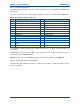
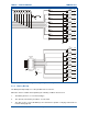
Digital Outputs are open collector able to sink 300 mA each; the total for all outputs must not
exceed 600 mA. See Figure 8 overleaf.
Digital inputs are active low. Digital high voltages should not exceed 20 V. See Figure 8.
GPS Rx and 1PPS Rx are Differential RS422.
The “Analogue Out” signal is between 0 V and 5 V and software controlled to indicate various
functions e.g. RSSI.