
User Manual

SDB670 – SERVICE MANUAL TNM-M-E-0032
May 13 Page 27 DESCRIPTION
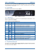
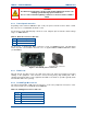
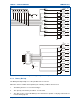
4.3.5 P3 USB A Duel
The USB Type A connector is used as the host connection. The connector pin-outs are detailed
below in Table 11.
Table 11. USB Type A Connector Pin-outs.
Pin Function
1 Vcc (+5 V)
2 Data -
3 Data +
4 Ground
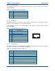
4.3.6 P5 Ethernet
The Ethernet socket is a 10/100 base-T RJ45 connection. The Ethernet socket provides a 10Base
Ethernet connection which is used for network connection.
The P5 Ethernet connector uses standard network cable wiring for an RJ45, which is detailed
below in Table 12.
Table 12. Ethernet RJ45 Connector Pin-outs.
Pin Description
1 Tx Data+, balanced I/P 1
2 Tx Data-, balanced I/P 2
3 Rx Data+, balanced O/P 1
4 NC
5 NC
6 Rx Data-, balanced O/P 2
7 NC
8 NC
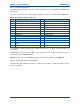
4.3.7 S2 Serial Port
The serial connection is a standard DB-9 female RS-232 socket. The connector pin-outs for the 9-
way D Type S2 Serial Port are shown below in Table 13.
Table 13. S2 Serial Port Connector Pin-outs.
Pin Function
1 Connected to pin 4 and 6
2 Tx 1
3 Rx 1
4 Connected to pin 1 and 6
5 0 V
6 Connected to pin 1 and 4
7 Rx 2 (opt CTS 1)
8 Tx 2 (opt RTS 1)
9 NC
1
8