
User Manual

SDB670 – SERVICE MANUAL TNM-M-E-0032
May 13 Page 25 DESCRIPTION
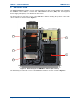
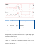
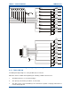
Figure 5. Layout of Rear Panel (AC version).
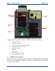
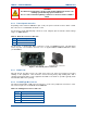
Figure 6. Layout of Rear Panel (DC version).
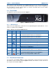
Table 8. Rear Panel Connections.
Connector #
Conn Type
Function Description
Power I/P 13.8 V DC power input
S2 RS232 Serial Port
S1 D Type Facilities
P5 RJ45 Ethernet 10/100 base-T RJ45 Ethernet connector
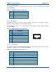
P4 USB Type B
Peripheral USB peripheral interface
P3 USB Type A
Host USB interface
Battery Backup
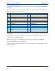
Tx N Type Tx O/P RF Power output from the Tx
Rx 1 BNC Rx I/P Rx input for full duplex operation
4.3.1 Tx/Rx Connections
The Tx antenna connection on the DMR Base is provided with 50 Ω female N-type socket, while
for the Rx antenna connection a BNC socket is used.
The Tx antenna cable connection must be made with 50 Ω N-type on a flexible tail. The Voltage
Standing Wave Ratio (VSWR) of Tx and Rx connections should be tested prior to use by using of a
suitable test set, e.g. an Anritsu/Wiltron S331A. A good VSWR of 1.5:1 or better at the relevant Tx
and Rx frequencies should be ensured.
Mating connectors should be galvanically compatible with nickel outer and gold centre pin to
minimise passive intermodulation.
A minimum of 85 dB transmit-receive isolation should be provided by the antenna system and
associated filters.
It is recommended that a good quality flexible co-axial cable is used, e.g. with double-screening
braid and multi-strand copper inner.